Device for controlling a venetian blind

a technology for venetian blinds and control devices, applied in the direction of door/window protective devices, light protection screens, doors/windows, etc., can solve the problems of not being able to enable such a blind to be lowered or raised, and the control of lines is generally done using lines,

Inactive Publication Date: 2008-04-22
MARITON
View PDF8 Cites 15 Cited by
  • Summary
  • Abstract
  • Description
  • Claims
  • Application Information

AI Technical Summary

Benefits of technology

[0012]According to the invention, one of the rings is prevented from rotating by means of a carriage provided with two pairs of teeth and movable horizontally in translation in such a manner as to prevent one only of the rings from rotating, while leaving the other one free to rotate.
[0013]For this purpose, and advantageously, the carriage is secured to a pair of claw clutches capable of preventing the rings from moving in rotation in such a manner that only one of the rings is prevented from moving in rotation while the other one remains free to rotate.

Problems solved by technology

That type of control using lines generally presents the drawback in that the lines easily become tangled together or twisted about each other.
None of the above-specified devices enables such a blind to be lowered or raised by the user performing the same simple action.

Method used


Image

  • Device for controlling a venetian blind
  • Device for controlling a venetian blind
  • Device for controlling a venetian blind

Examples


Embodiment Construction

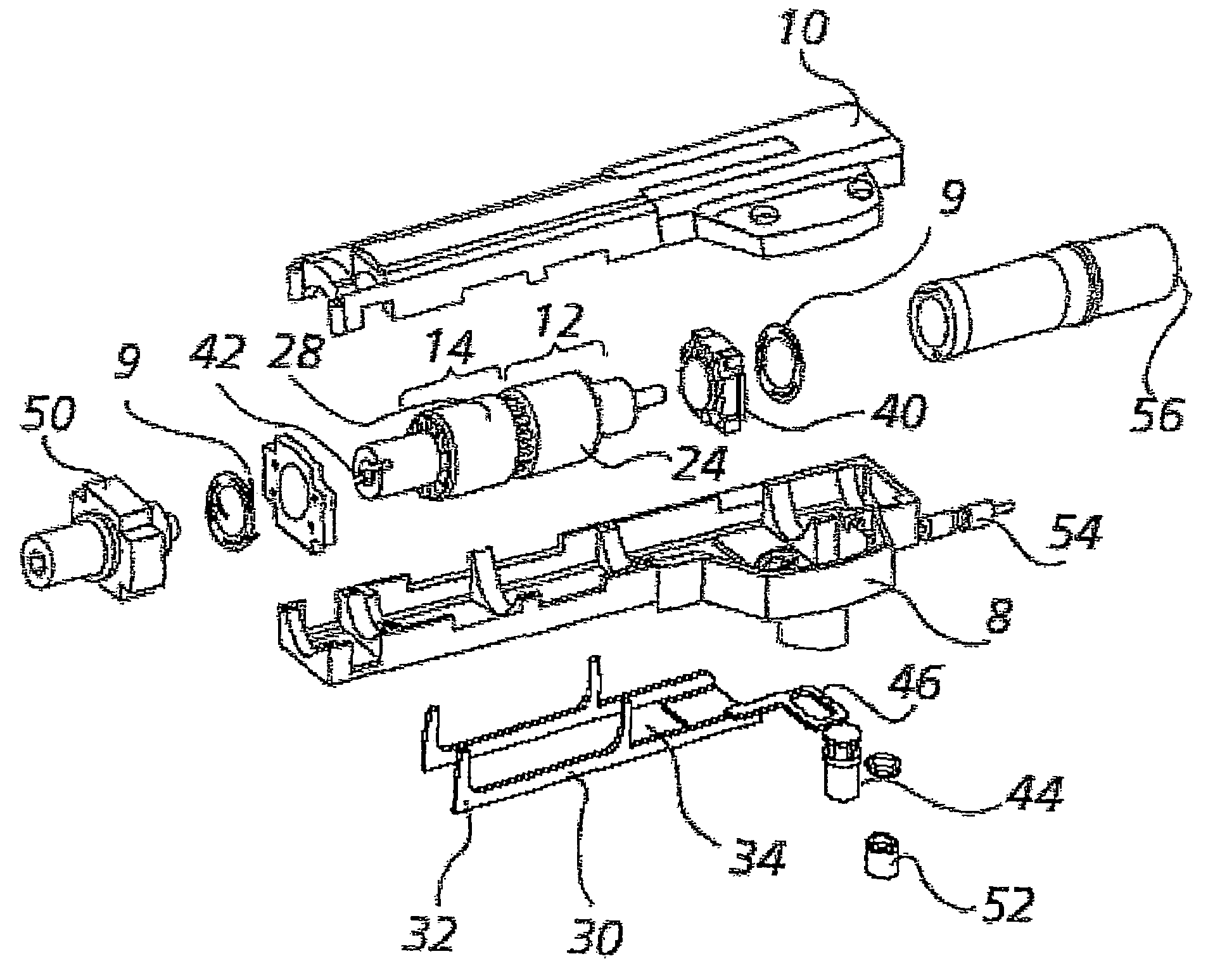
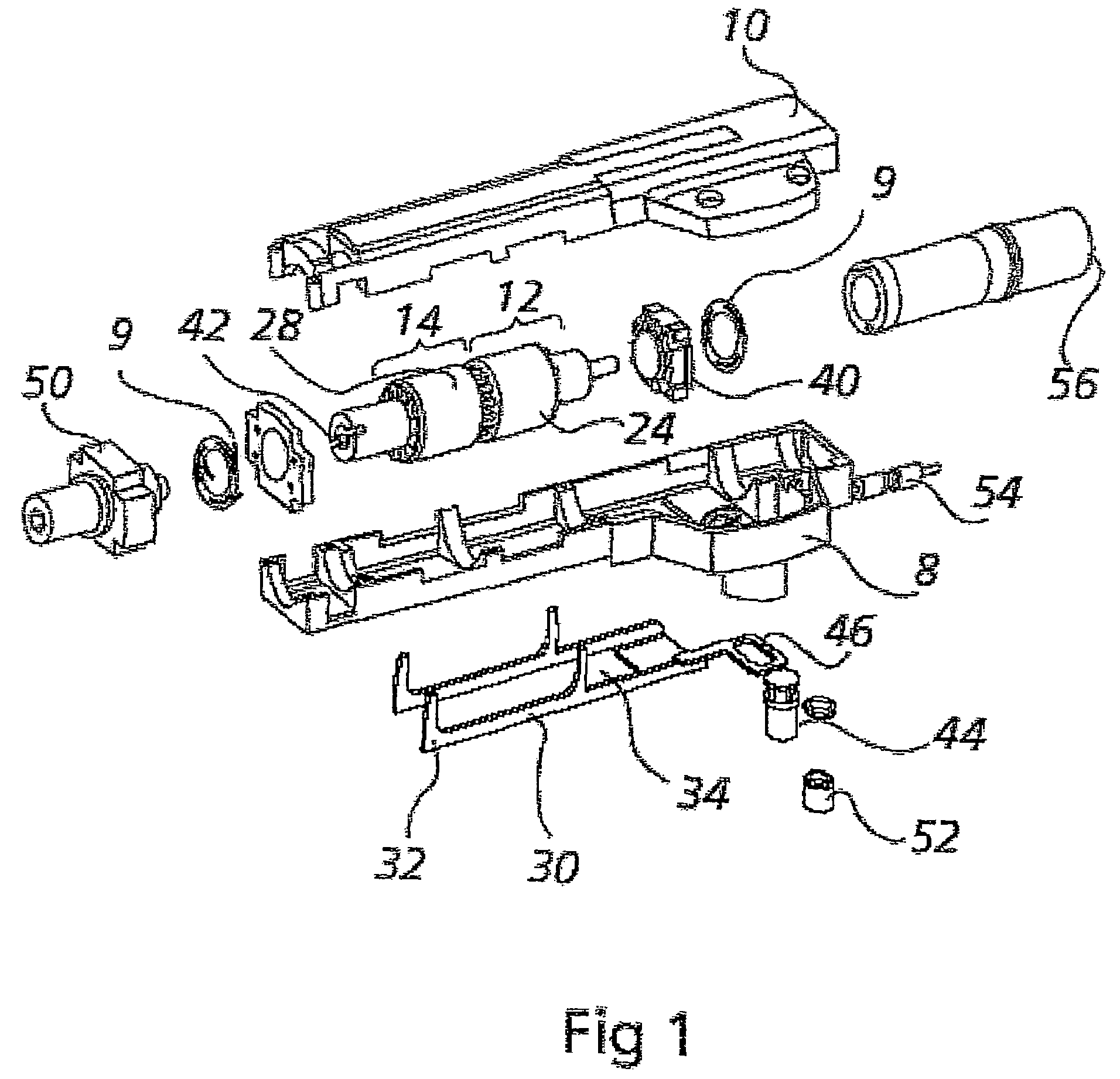
[0022]Reference is now made to the figures briefly summarized above. The blind itself is not shown as such in the figures, since it is well known to the person skilled in the art. Nevertheless, FIGS. 5A and 5B show the blind in part in association with the device for controlling the blind.

[0023]In general, a blind comprises a vertically deployable panel made up of horizontal slats supported by ribbon ladders and terminated by a bottom end horizontal bar whose position is determined by means of at least two cords or tapes suitable for being wound on a horizontal driven roller (not shown in the figures).

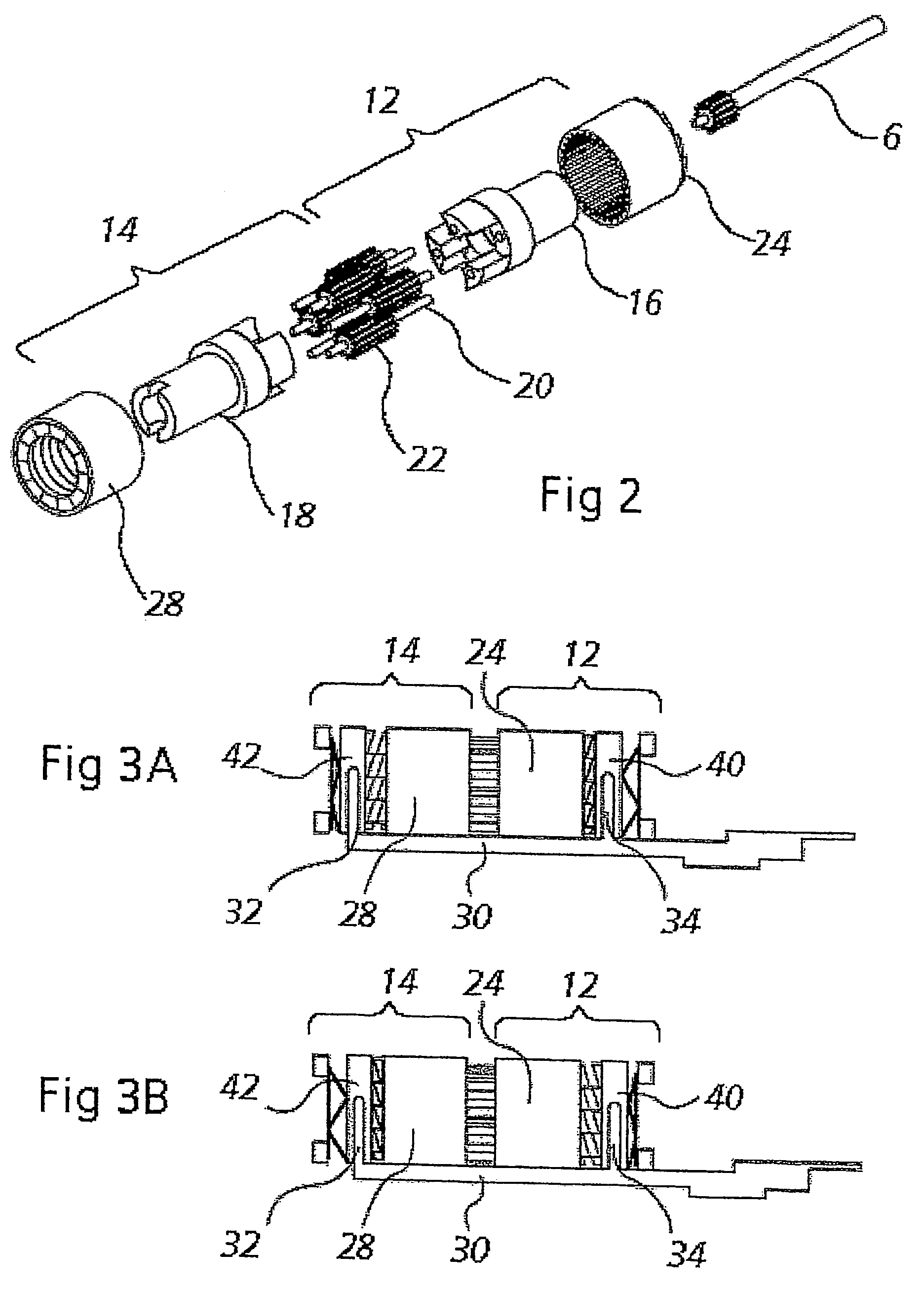
[0024]A top module, as shown in FIG. 1, comprises a device that transforms rotary movement of a horizontal drive roller 6 into rotary movement of another roller, a horizontal driven roller which is rotated in a determined direction.

[0025]The top module is constituted by a casing made up of a bottom 8 and a cover 10 enclosing the mechanism for transforming the rotary movement.

[0026]The ...


PUM


Abstract

The invention relates to a device for controlling a venetian blind, the device comprising a top module for transforming rotary movement of a horizontal drive roller into rotary movements in a determined direction a horizontal driven roller. According to the invention, the top module contains first and second epicyclic gear trains connected in series, each gear train presenting a set of parallel-shafted planet gears meshing in a respective ring and containing a rotary planet carrier, the direction of rotation of the planet gears of one of the trains being reversed relative to that of the planet gears of the other one of the trains by mutual meshing, the planet gears of the second rotary planet carrier being rotated by the horizontal drive roller, while the second rotary planet carrier is constrained to rotate with the horizontal driven roller.

Description

[0001]The invention relates to controlling blinds of the venetian blind type having horizontal slats.BACKGROUND OF THE INVENTION[0002]In general, such a blind comprises a vertically-deployable panel made up of horizontal slats supported by ribbon ladders and terminated by a horizontal bottom end bar of position that is determined by means of at least two cords suitable for being wound on a horizontal driven roller of a top module that transforms rotary movement of a horizontal drive roller into rotary movement in a determined direction of said horizontal driven roller, as is well known in the art.[0003]In general, each rung of the ribbon ladder carries a substantially horizontal blade that is tiltable about this relative horizontal direction in order to adjust its angle and obstruct the access of light to a greater or lesser extent.[0004]Blinds of this type thus require a plurality of separate controls, in particular for raising or lowering the horizontal bottom bar and for tilting ...

Claims


Application Information

Patent Timeline
Patent Type & Authority Patents(United States)
IPC IPC(8): E06B9/30E06B9/303E06B9/32E06B9/322
CPCE06B9/303E06B9/322
Inventor MAUMI, PIERRE-LUCPASSINI, LAURENTQUILLOT, DOMINIQUE
Owner MARITON
Why Eureka
Try Eureka