Compressor
- Summary
- Abstract
- Description
- Claims
- Application Information
AI Technical Summary
Benefits of technology
Problems solved by technology
Method used
Image
Examples
Embodiment Construction
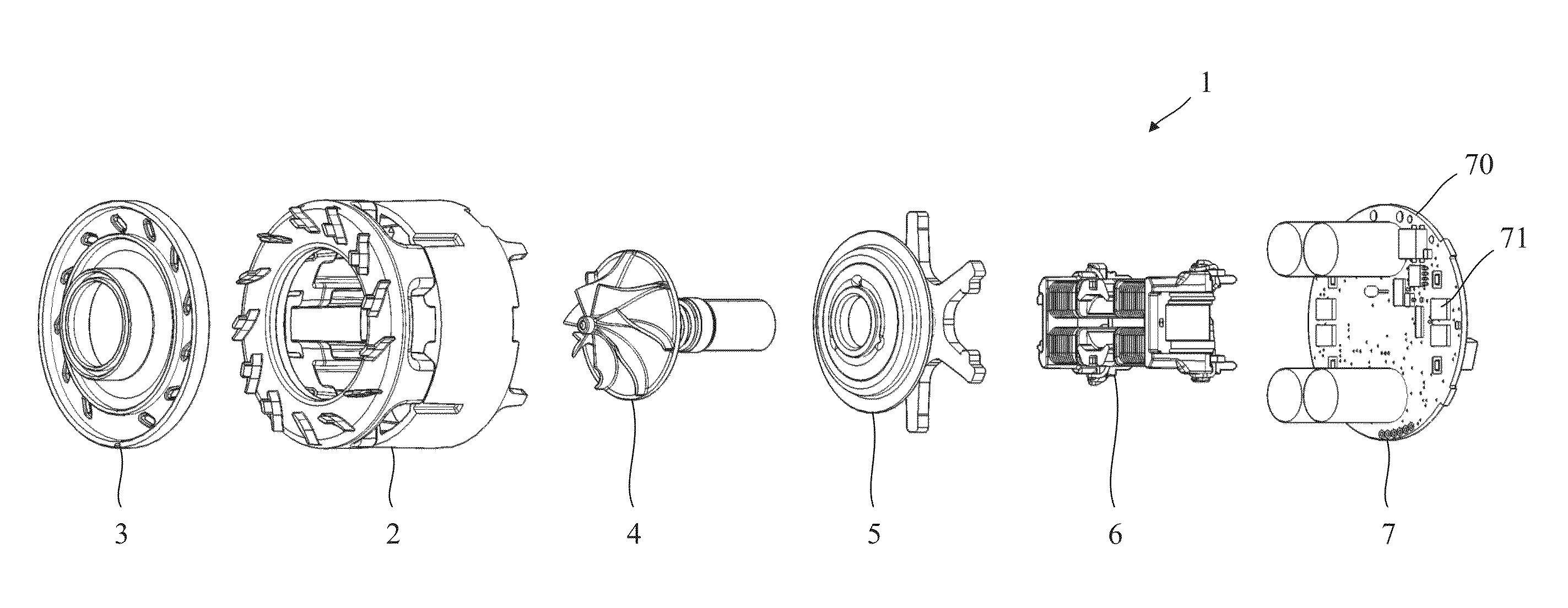
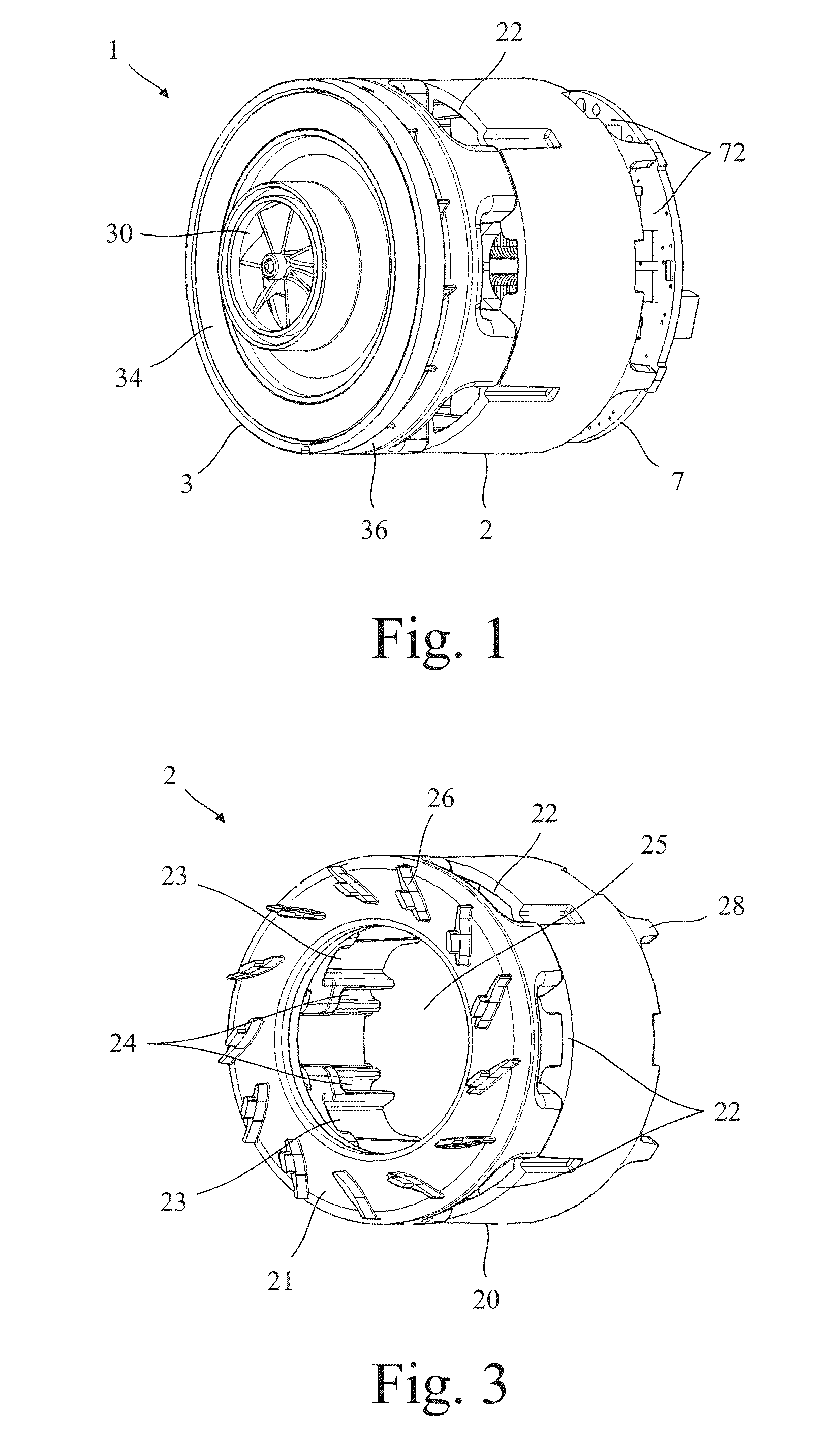
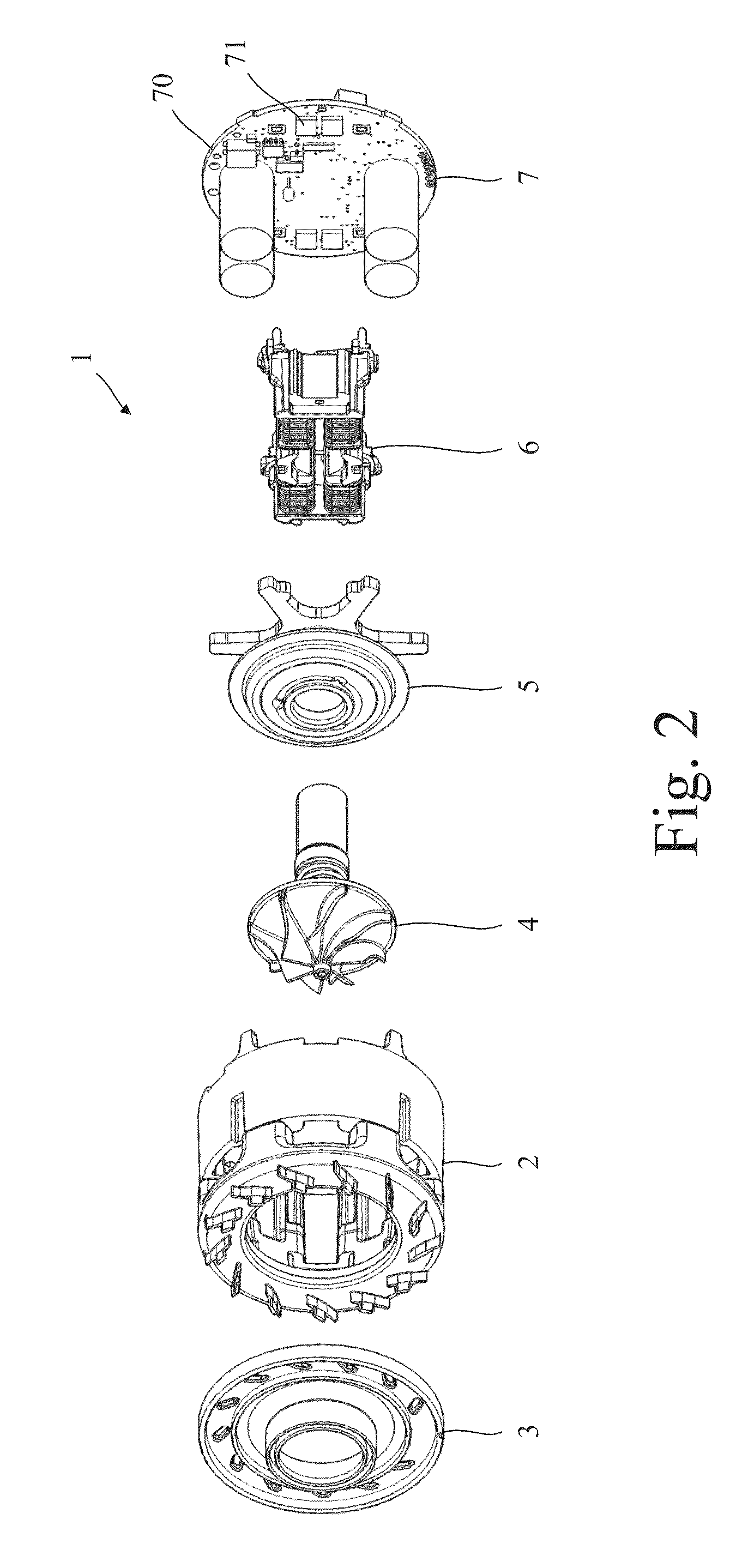
[0042]The compressor 1 of FIGS. 1 to 11 comprises a frame 2, a shroud 3, a rotor assembly 4, a heat sink assembly 5, a stator assembly 6, and a circuit assembly 7.
[0043]The frame 2 is generally cylindrical in shape and comprises a side wall 20, an end wall 21, a plurality of inlet apertures 22 located around the side wall 20, a plurality of pockets 23 and a plurality of channels 24 located on the inside of the side wall 20, a central aperture 25 located in the end wall 21, and a plurality of diffuser vanes 26 located around the end wall 21. The pockets 23 and the channels 24 take the form of recesses that extend axially along the inside of the side wall 20. The recesses are open at one end (distal the end wall 21) and closed at the opposite end (proximal the end wall 21). The end wall 21 is located at one end of the side wall 20 and resembles an annulus around which the diffuser vanes 26 are located. The opposite end of the side wall 20 is open and terminates with a plurality of pro...
PUM
 Abstract
Description
Claims
Application Information
 - R&D
- Intellectual Property
- Life Sciences
- Materials
- Tech Scout
- Unparalleled Data Quality
- Higher Quality Content
- 60% Fewer Hallucinations
Browse by: Latest US Patents, China's latest patents, Technical Efficacy Thesaurus, Application Domain, Technology Topic, Popular Technical Reports.
© 2025 PatSnap. All rights reserved.Legal|Privacy policy|Modern Slavery Act Transparency Statement|Sitemap|About US| Contact US: help@patsnap.com


