Mounting concept for an electric axle

a technology of mounting concept and electric axle, which is applied in the direction of toothed gearings, vehicle sub-unit features, and drive control systems of road vehicles

Active Publication Date: 2016-09-13
SCHAEFFLER TECH AG & CO KG
View PDF20 Cites 5 Cited by
  • Summary
  • Abstract
  • Description
  • Claims
  • Application Information

AI Technical Summary

Benefits of technology

[0004]It is an object of the present invention to provide a rugged and space-saving electric drive system for powering a motor vehicle.
[0006]In addition, the drive system according to the present invention includes a superimposing transmission and a power divider having a first power divider shaft that drives a first output shaft, and has a second power divider shaft that drives a second output shaft. The aforesaid power divider makes possible different rotational speeds on the left and right output sides, as is known from conventional differential gears.
[0011]To begin with, the ruggedness of the drive system is ensured because neither of the output shafts contacts the rotor shaft or any one of the transmission assemblies at any location. Also, the fact that the transmission input shaft is additionally vibrationally decoupled from the rotor shaft contributes to the mechanical resistance of the system. This decoupling is achieved in that the two shafts are first intercoupled axially displaceably, for example with the aid of a spline toothing. This decoupling is further achieved in that the end of the transmission input shaft facing the rotor shaft is radially supported separately at the further bearing point on the housing. Accordingly, the rotor shaft is decoupled both from the transmission input shaft, as well as from the output shafts. Therefore, the mounting concept according to the present invention makes possible the highly precise mounting of the rotor, while maintaining a small air gap, even under strong mechanical excitations of the output shafts.
[0012]One advantageous embodiment of the present invention provides that the first rotor shaft be mounted via two rolling element bearings having a rotating outer ring and a stationary inner ring. This ensures a space-saving configuration and ease of mounting. In addition, when a rotating outer ring is used, a low seal friction is obtained at a high speed. Moreover, balancing of the rotor is still possible, even in the pre-mounted state.
[0018]The power divider of the axle drive system is advantageously configured as a planetary differential, a planetary carrier of the planetary differential being connected to the first output shaft for co-rotation therewith, and a sun gear of the planetary differential being connected to the second output shaft for co-rotation therewith; and the second drive motor being operatively engaged via a spur gear stage with the sun gear of the fourth planetary gear set; and a ring gear of the fourth planetary gear set being connected to the planetary carrier of the planetary differential for co-rotation therewith. The aforesaid spur gear stage steps down the speed of the second drive motor, thereby making possible a compact enough realization of the same. The radial bracing of the output sun and of the output carrier of the planetary differential is assumed by the sun, and that of the output carrier of the planetary differential by the output shafts of the axle drive system.
[0020]Another advantageous embodiment of the present invention is characterized in that the entire transmission unit, including the superimposing transmission, the power divider, and the planetary gear unit of the torque vectoring unit, is axially preloaded by axial bearings that all have the same pitch circle; considered axially, the aforesaid transmission unit being clamped between the first and the second drive motor. Thus, a compact design is derived for the complete axle drive unit, where the transmission components, an advantageously present switchable coupling and the actuator system thereof are configured between the first and second drive motor and are clamped there. Needle bearings are used, for example, for the axial mounting. In one advantageous embodiment, they are all configured on the same pitch circle, thereby allowing tilting moments within the axle drive system to be absorbed very effectively.

Problems solved by technology

The output shafts coupled to the wheels are subject to enormous mechanical loads during travel.

Method used


Image

  • Mounting concept for an electric axle
  • Mounting concept for an electric axle

Examples


Embodiment Construction

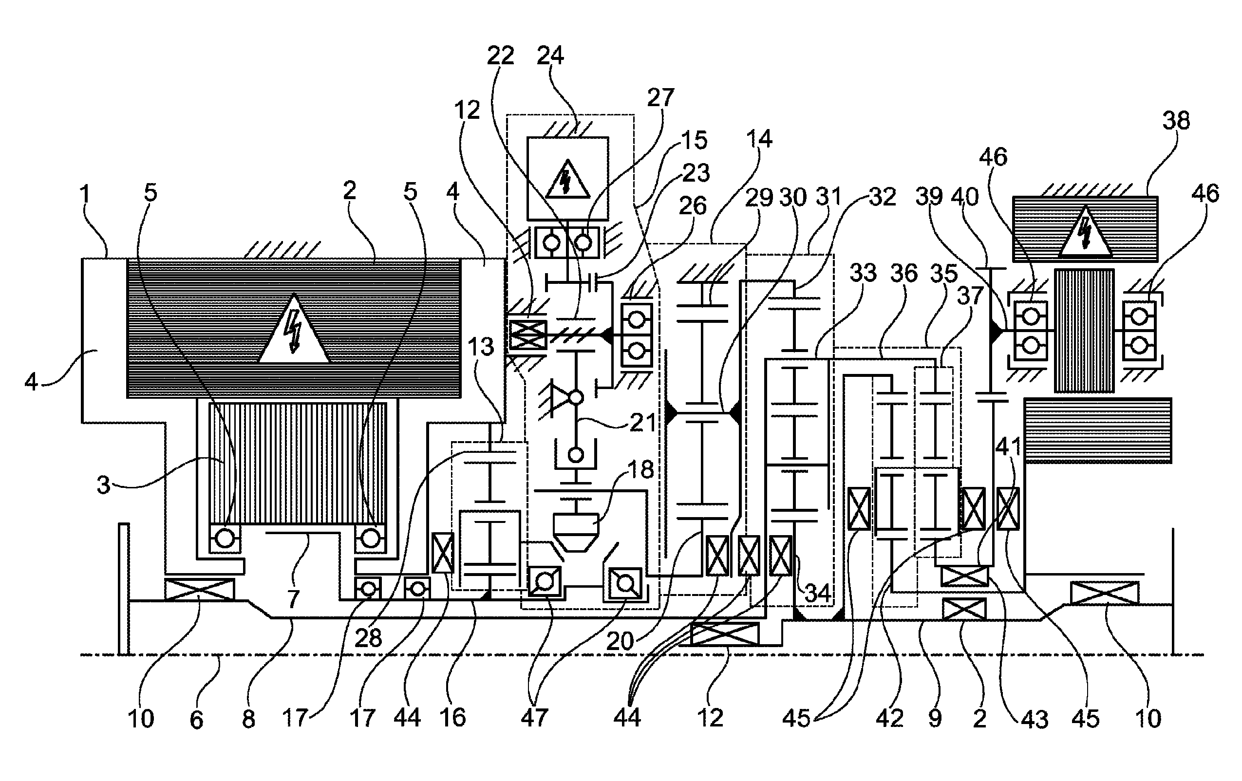
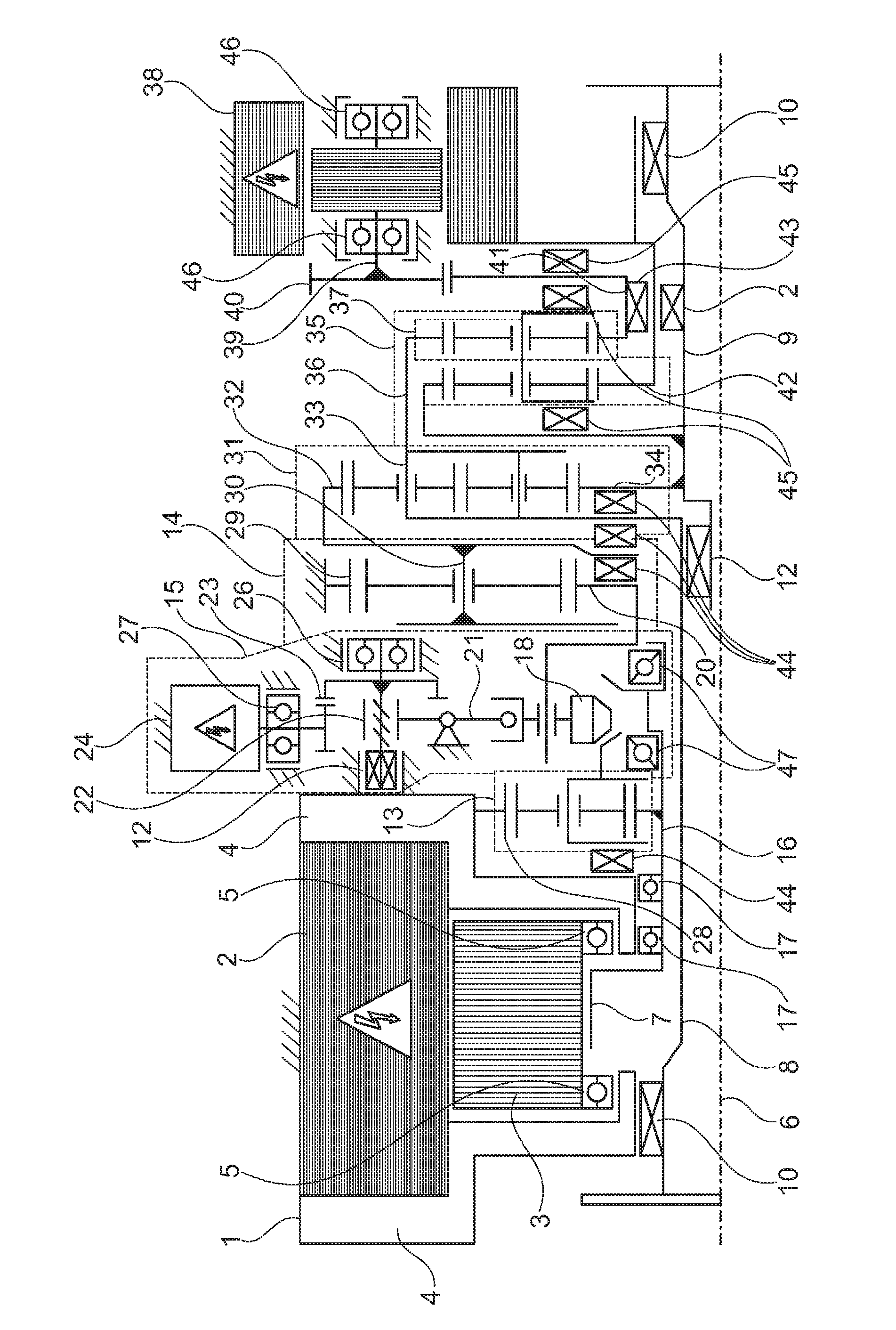
[0023]The figure shows a specific embodiment of an axle drive system along the lines of the present invention, including a schematic representation of the bearing points. To begin with, the axle drive system includes a first dynamoelectric drive motor 1 that applies the torque for driving a motor vehicle axle. First drive motor 1 includes an external stator 2 that is spaced apart from an internal rotor 3 by an air gap. Stator 2 and rotor 3 are accommodated in a machine housing, whose end shields 4, which abut on the end faces of the machine, are discernible in the FIGURE. The rotor of first drive motor 1 is braced radially against end shields 4 via two grooved ball bearings 5.

[0024]In this case, the mounting is such that the outer ring of grooved ball bearing 5 rotates together with rotor 3 about axis of rotation 6, while the inner ring of grooved ball bearing 5 is stationary in each case. Rotor 3 includes a rotor laminated core that is shrunk-fit onto first rotor shaft 7 configured...


PUM


Abstract

An axle drive system includes a first dynamoelectric drive motor having a first rotor shaft radially mounted on a housing at two bearing points; a superimposing transmission and a power divider having a first power divider shaft driving a first output shaft, and having a second power divider shaft driving a second output shaft; the power divider shafts, the output shafts and the first rotor shaft rotationally mounted about a common axis of rotation oriented transversely to the direction of travel. A transmission input shaft is connected to the first rotor shaft for co-rotation therewith; at one end facing the first rotor shaft, the transmission input shaft is radially mounted on the housing at a further bearing point; the first rotor shaft and the transmission input shaft are intercoupled axially displaceably; the first and the second output shafts are each mounted relative to the housing by a radial bearing and relative to each other by another radial bearing.

Description

[0001]The present invention relates to an axle drive system for a motor vehicle. Such an axle drive system is used, for example, in electrically powered vehicles or in hybrid vehicles. The axle drive systems of the aforementioned type are characterized by a coaxial configuration of a dynamoelectric drive motor provided for electric propulsion, a superimposing transmission that reduces rotational speed, and a power divider for distributing the torque generated by the drive motor to the output shafts. In an axle drive system of the above-mentioned type, the aforesaid three components have a common axis of rotation that is oriented transversely to the direction of travel of the motor vehicle.BACKGROUND[0002]An axle drive system for a motor vehicle having the features set forth in the definition of the species in claim 1 is generally known from the German Patent Application DE 102010036884 A1. The coaxial design of the axle drive system and the nested configuration of the output shafts ...

Claims


Application Information

Patent Timeline
Patent Type & Authority Patents(United States)
IPC IPC(8): F16H3/72F16H48/10F16H37/08B60K1/00B60K1/02F16H57/02F16H48/36F16H48/40F16H63/30
CPCF16H37/082B60K1/00B60K1/02F16H48/10F16H48/36B60K2001/001B60Y2300/82B60Y2400/804F16H2048/364F16H2048/405F16H2057/02034F16H2063/3063
Inventor SMETANA, TOMAS
Owner SCHAEFFLER TECH AG & CO KG
Why Eureka
Try Eureka