Adjustable extended focus raman system

a raman and extended focus technology, applied in the field of raman spectroscopy, can solve the problems of contamination of samples, cast doubts on the integrity of sampling methods by untrained personnel, and not normally an option, so as to reduce the chance of mechanical failure, reduce the complexity of the device, and appreciate the simplicity and ruggedness of the moving elements.

Pending Publication Date: 2021-06-24
THERMO SCI PORTABLE ANALYTICAL INSTR INC
View PDF5 Cites 2 Cited by
  • Summary
  • Abstract
  • Description
  • Claims
  • Application Information

AI Technical Summary

Benefits of technology

[0012]For use in handheld analysis device where simplicity and ruggedness of the moving elements is appreciated. The movement of just a single component in the optical design is advantageous as it reduces the complexity of the device and reduces the opportunities for mechanical failure. The simple linear motion also allows for more rugged solutions amenable to the handheld application space.
[0013]This invention is intended for use by field personnel in outdoor environments as opposed to laboratory personnel in controlled environments. This use model necessitates a high level of automation, ruggedness, and highly values ease-of-use. The automated system control of spot size and / or detection size allows for use of the device with a minimum level of expertise in spectroscopy. The desire to minimize the complexity and increase the robustness can also be appreciated in the field-use application.
[0014]We have disclosed a design producing a distributed illumination spot with lower intensity near the center, and a means of collapsing the spot into a tight focus. The lower intensity of the distributed spot near the center allows for collecting Raman scattering spectra of materials inside a package, while the tighter focus spot allows sampling the packaging material spectrum so that it may be later subtracted from spectra containing both sample and packaging components.

Problems solved by technology

While the problem of fluorescence can be avoided completely by removing the material from its container, in field applications this is not normally an option.
Sampling can also cause contamination of the sample or cast doubts on the integrity of the sampling method by untrained personnel.
A fundamental problem with sampling through a container wall is that the packaging materials cause excessive fluorescence signal potentially obscuring the Raman signal from the material under test (e.g. diffuse scattering).

Method used


Image

  • Adjustable extended focus raman system
  • Adjustable extended focus raman system
  • Adjustable extended focus raman system

Examples


Embodiment Construction

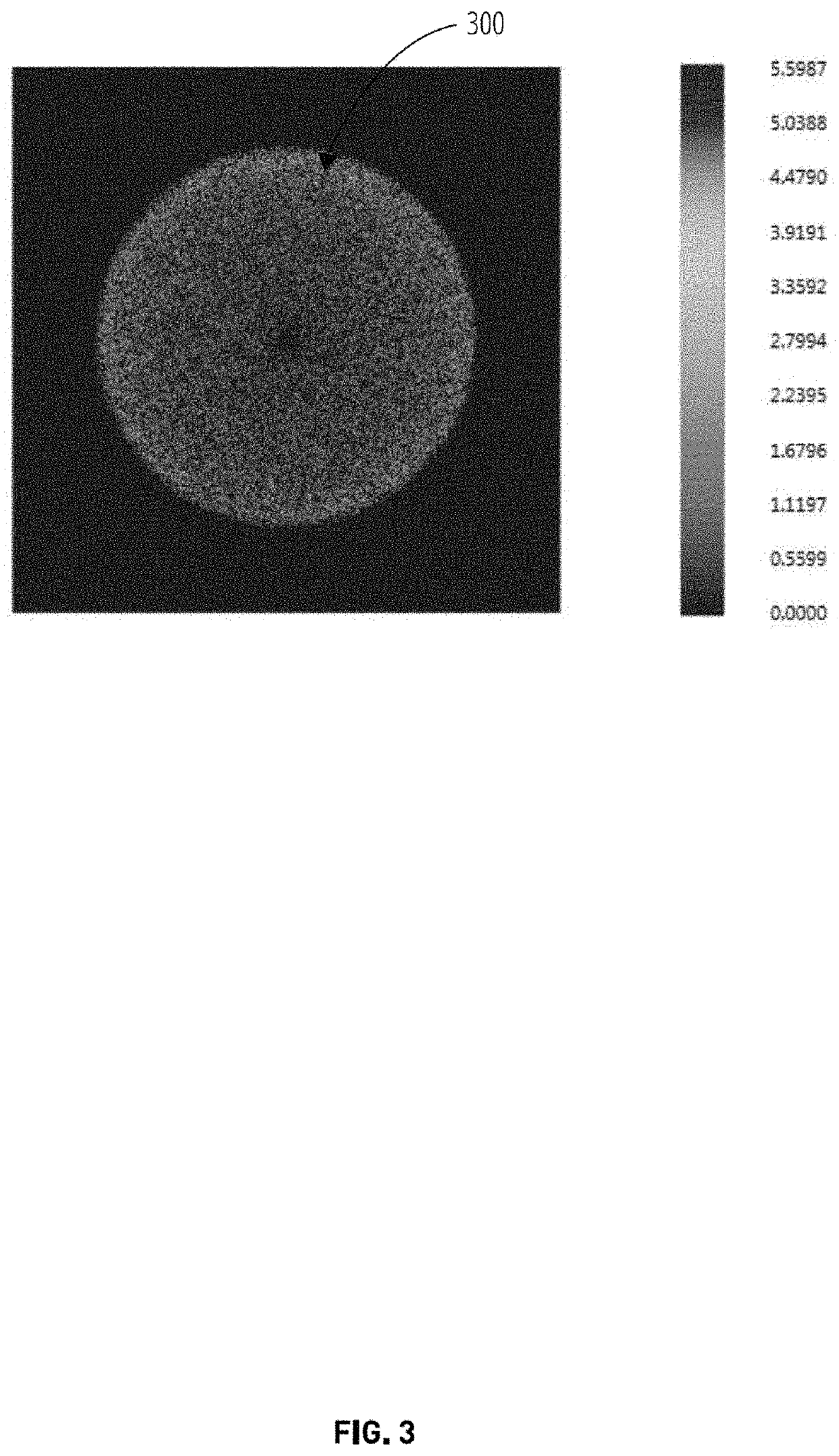
[0025]““traditional” Raman measurement” refers to a Raman system where the illumination spot diameter remains fixed size and has a uniform radial distribution

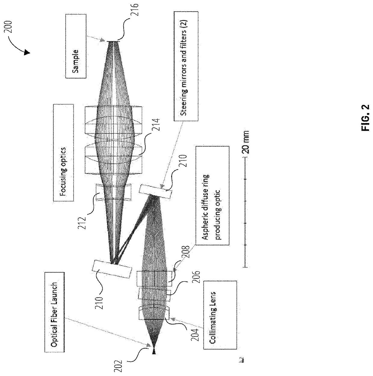
[0026]“Aspheric diffuse ring producing optic” refers to One embodiment for producing the distributed spot includes an aspheric diffuse ring producing optic, or ADRPO. For example, embodiments of aspheric optics may include what is referred to as an axicon or conical optic which produces a ring of intensity but has higher order aspheric terms to produce the spread-out pattern. In the described example the aspheric optic may have coefficients of A1=−0.01, A2=−0.06, and A4=0.002, with all other terms being zero.

[0027]“Collimating lens” refers to optical elements that transform the incoming light direction to parallel paths

[0028]“Filter” refers to optical elements that remove some wavelengths of incoming light

[0029]“Focusing optics” refers to optical elements that transform the incoming light direction to a point in space

[0030]“Lig...


PUM

PropertyMeasurementUnit
distanceaaaaaaaaaa
diameteraaaaaaaaaa
sizeaaaaaaaaaa

Abstract

An embodiment of a system is described that comprises a light source configured to produce a light beam; a collimating lens disposed on a movable mount, wherein the collimating lens is configured to capture the light beam and produce a substantially collimated beam; and an aspheric diffuse ring optic configured to receive the collimated beam and produce a spot on a surface that comprises a non-uniform radial intensity distribution.

Description

CROSS-REFERENCE TO RELATED APPLICATIONS[0001]The present application claims the priority benefit from U.S. Patent Application Ser. No. 62 / 950,837, filed Dec. 19, 2019, which is hereby incorporated by reference herein in its entirety for all purposes.FIELD OF THE INVENTION[0002]The invention generally relates to an apparatus for conducting Raman spectroscopy which utilizes an aspheric diffuse ring producing optic, or ADRPO, to generate an illumination spot with a variable radial intensity and a simple movable optic to alter the diameter of the illumination spot.BACKGROUND[0003]Optical scanning methods such as Raman spectroscopy can provide useful information about unknown materials. By identifying unknown materials, certain threats posed by hazardous materials can be reduced or eliminated. While the problem of fluorescence can be avoided completely by removing the material from its container, in field applications this is not normally an option. Sampling can also cause contamination ...

Claims


Application Information

Patent Timeline
Patent Type & Authority Applications(United States)
IPC IPC(8): G01N21/65G02B7/10G02B27/09G02B27/30
CPCG01N21/65G02B7/10G02B27/0955G02B27/30G01N2201/0636G01N2201/06113G01N2201/062G01N2201/0633G02B27/0927G01N2201/063G01J3/44G01J3/0208G01J3/0205G01J3/0237G01J3/10G01N2201/0221
Inventor SMITH, MALCOLM C.
Owner THERMO SCI PORTABLE ANALYTICAL INSTR INC
Why Eureka
Try Eureka