System and method for sensing the periodic position of an object

a technology of periodic position and sensing method, which is applied in the field of electronic equipment, can solve the problems of insufficient bandwidth of combined resistance and inductance of wire and coil, inability to accurately measure the output signal of passive eddy current sensors, and inability to detect the position of objects with periodic position, etc., to achieve the effect of greater target sensitivity, high bandwidth capability and rugged circuitry

US8018225B2Active Publication Date: 2011-09-13GENERAL ELECTRIC CO
12 Cites 5 Cited by

Patent Information

Authority / Receiving Office
US · United States
Patent Type
Patents(United States)
Current Assignee / Owner
Publication Date
2011-09-13

Smart Images

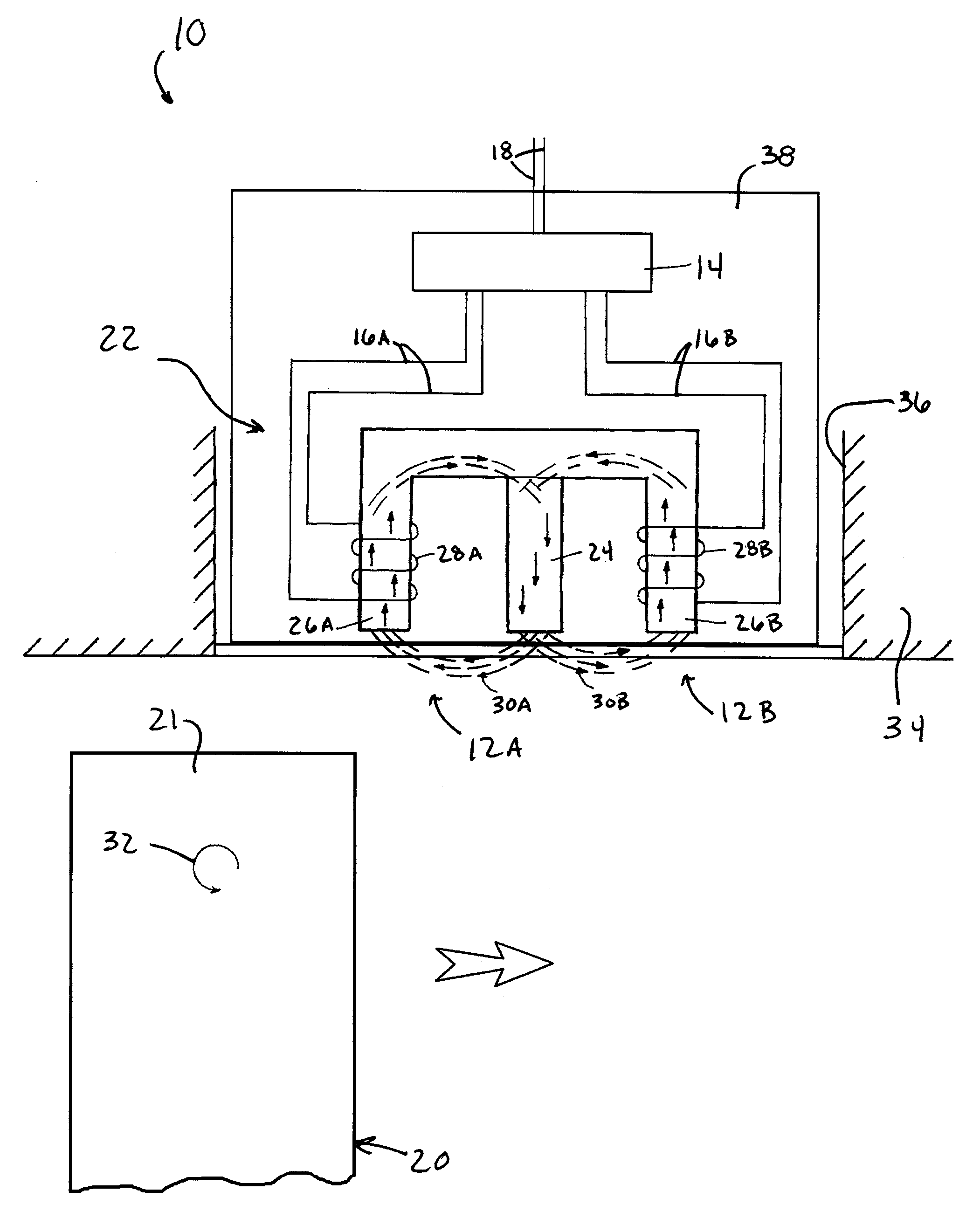
  • Figure 1
    Figure 1
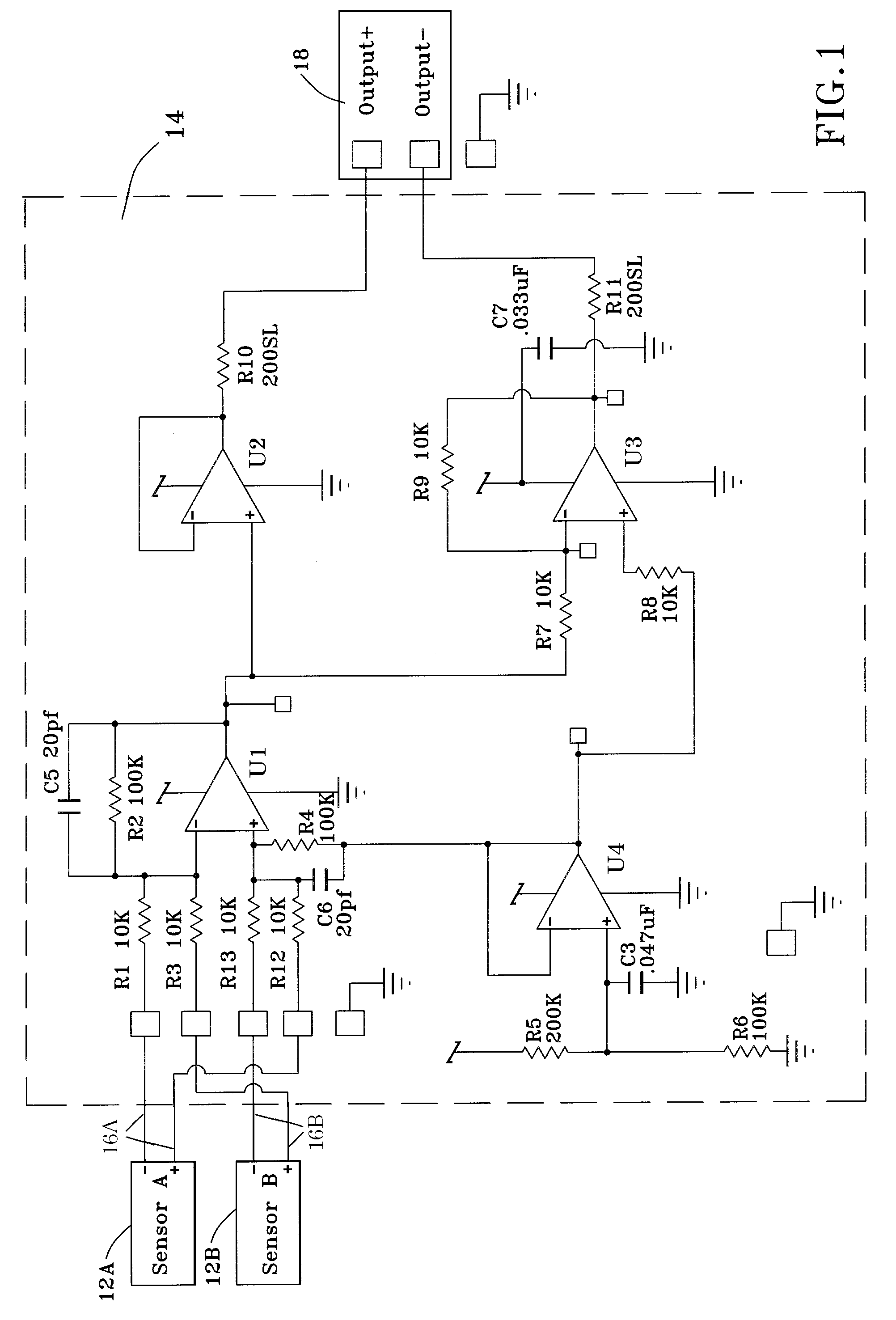
  • Figure 2
    Figure 2
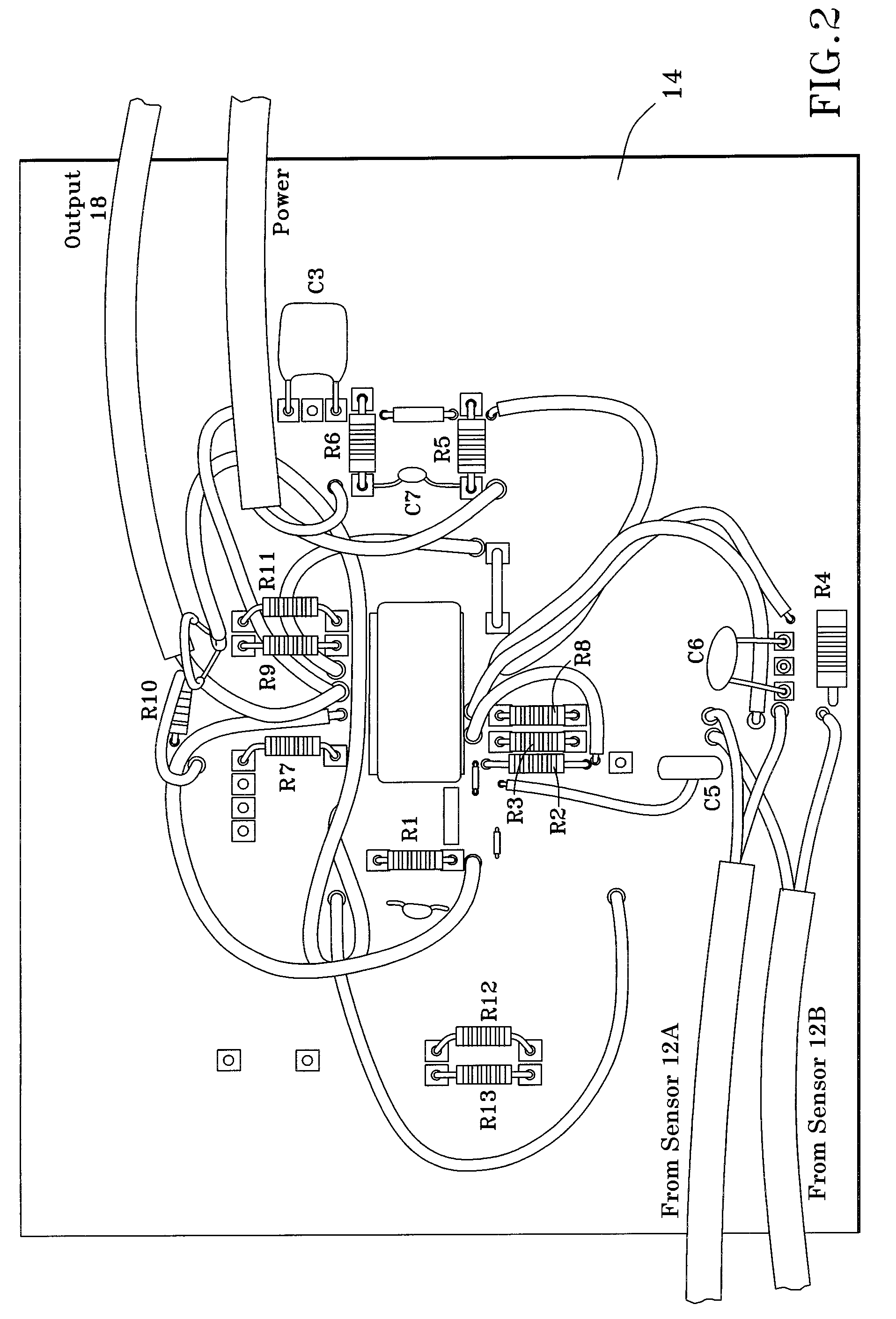
  • Figure 3
    Figure 3
Patent Text Reader

Abstract

A system and method for sensing the periodic position of one or more objects, such as rotating blades of a turbine. The system includes a passive eddy current sensing unit having one or more magnets and first and second cores around which first and second coils are wound, respectively, which together generate first and second magnetic fields. The sensing unit is positioned so that the object periodically passes through the first and second magnetic fields in succession, and the first and second coils consequently produce first and second output signals, respectively. Each coil is individually connected to a processing circuitry that receives each of the first and second output signals. The circuitry electronically combines the first and second output signals so that common mode signals thereof electronically subtract from each other to eliminate from output of the circuitry any electromagnetic interference noise present in the first and second output signals.
Need to check novelty before this filing date? Find Prior Art

Description

BACKGROUND OF THE INVENTION

[0001] The present invention generally relates to electronic equipment, and more particularly to a system that utilizes passive eddy current sensors to sense rotating equipment, such as the arrival, position, and / or vibration of turbine blades and other moving objects.

[0002] Passive eddy current sensors and variable reluctance sensors have been employed in a wide variety of applications to sense the proximity and speed of rotating equipment, including blades (buckets) of gas turbines. Another application is to sense the positions of rotating blades within the fan, booster, compressor and turbine sections of a gas turbine engine to monitor the health of the engine. In particular, the output of a passive eddy current sensor (or other suitable position sensor) can be used to monitor blade vibrations and steady-state blade circumferential positions over the life of the engine. Changes in blade vibrations or blade static positions can indicate damage to the compo...

Examples

Embodiment Construction

[0019]FIG. 1 is an electrical schematic of a sensing system 10 containing two passive eddy current sensors 12A and 12B coupled to analog electronic processing circuitry 14 that electronically combines separate output signals 16A and 16B of the sensors 12A and 12B, respectively. The processing circuitry 14 combines the output signals 16A-B of the sensors 12A-B in a manner that eliminates EMI noise from the system output 18 generated by the circuitry 14 by canceling any EMI noise present in the output signals 16A-B of the sensors 12A-B, as well as provides gain to the output signals 16A-B, with the result that the system 10 is also capable of exhibiting a high bandwidth capability and greater target sensitivity. The system 10 and sensors 12A-B will be discussed as particularly well suited for sensing the position of rotating equipment, such as blades (buckets) 20 of a gas turbine engine as represented in FIG. 4, though other applications are foreseeable. In such an application, after ...