Wideband traveling wave microstrip antenna

a microstrip antenna and traveling wave technology, applied in the direction of radiating element structure, resonance antenna, antenna earthing, etc., can solve the problems of limited bandwidth of microstrip antennas, large antennas, complex feed configurations, etc., to suppress the resonant behavior of microstrip antennas, and improve the performance of microstrip antennas.

Inactive Publication Date: 2007-12-11
UNITED STATES OF AMERICA
View PDF12 Cites 11 Cited by
  • Summary
  • Abstract
  • Description
  • Claims
  • Application Information

AI Technical Summary

Benefits of technology

[0007]It is a general purpose and object of the present invention to disclose a microstrip antenna that achieves superior bandwidth performance.
[0008]It is a further object of this invention to achieve superior band width performance by suppressing the resonant behavior of the microstrip antenna through distributed reactive loading.
[0009]The above objects are achieved with the present invention by propagating a traveling wave of electric current along a microstrip antenna structure rather than a standing wave. By loading an antenna with a series of capacitive gaps of the correct values, the shape of the electric current distribution can be tailored to suppress the resonant properties of the antenna. A microstrip antenna having a “bulls-eye target” structure comprised of a central disk and concentrically larger capacitively coupled annular sections will tailor the shape of the electric current distribution to achieve a suppression of the resonant properties of the antenna, thereby increasing the antenna bandwidth.

Problems solved by technology

In the past, microstrip antennas have been used in numerous forms and applications, but all of them suffered from the limitation imposed by their inherent narrow bandwidths.
This led to antennas that were large, had complex feed configurations, and were very expensive to produce and operate.
This standing wave can only be efficiently supported when the antenna's length is a multiple of a half wavelength (for center-fed dipole antennas).
As the antenna's length moves away from these select wavelengths, the antenna will not operate efficiently, hence limiting its bandwidth.

Method used


Image

  • Wideband traveling wave microstrip antenna
  • Wideband traveling wave microstrip antenna

Examples


Embodiment Construction

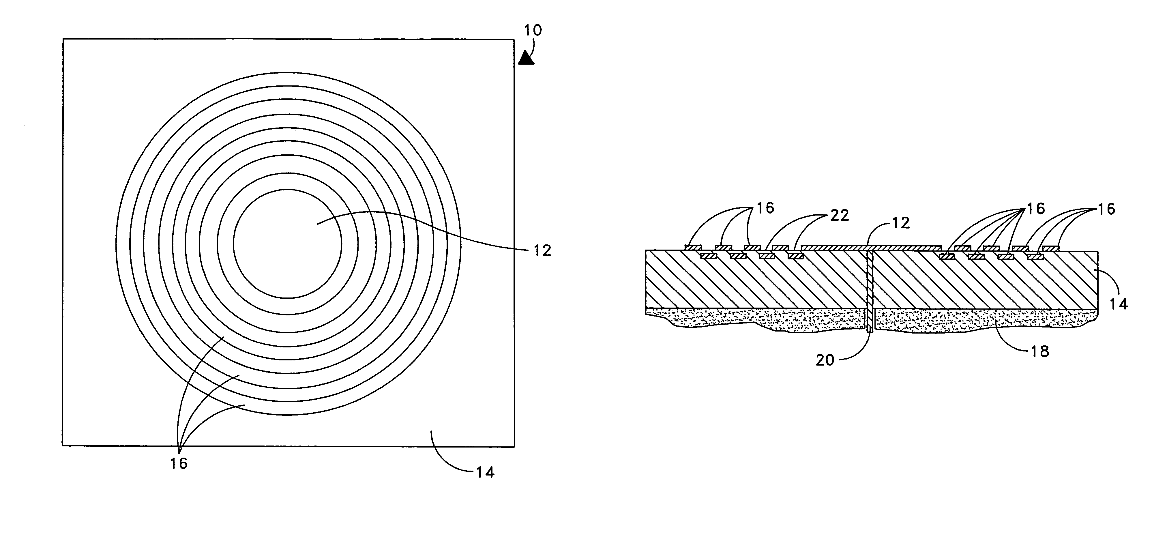
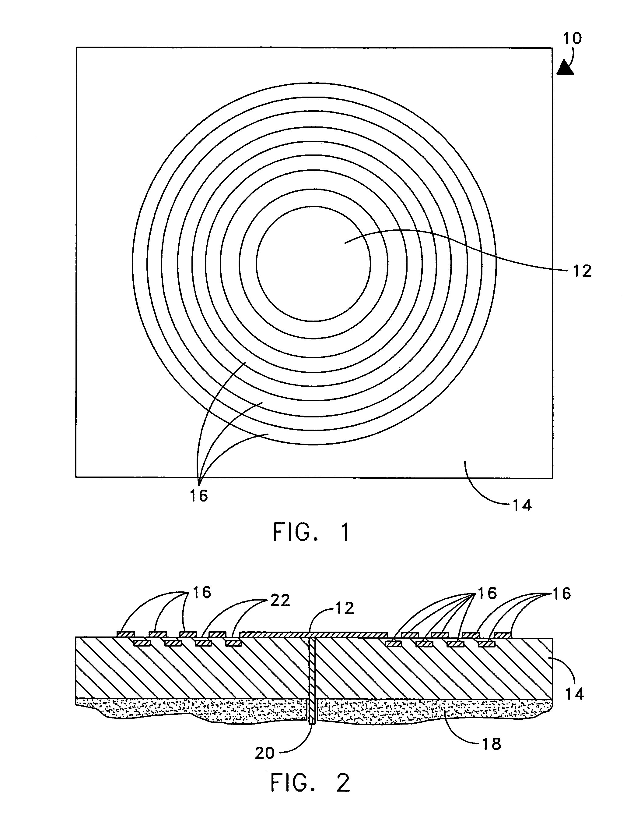
[0013]Referring to FIG. 1 and FIG. 2, there is shown a microstrip patch antenna 10 having a “bulls-eye target” configuration. The antenna consists of a center disk 12, which is a conductor, positioned on a dielectric substrate 14. The dielectric substrate is positioned on a ground plane 18. The antenna also consists of annular sections 16 each having a different diameter. Each annular section 16 is also a conductor. The annular sections 16 are situated both on the surface of the dielectric substrate 14 and embedded beneath the surface of the dielectric substrate 14. The size of the annular sections 16 depends on the frequency of the antenna. Typically, a minimum of 5 or 6 segments are needed to create enhanced bandwidth, the greater the number of segments, the greater potential for increased bandwidth. The annular sections 16 are arranged in a progressively concentric pattern starting from the center disk 12 such that each annular section 16 on the surface of the dielectric substrat...


PUM


Abstract

The present invention by propagates a traveling wave of electric current along a microstrip antenna structure rather than a standing wave. By loading an antenna with a series of capacitive gaps of the correct values, the shape of the electric current distribution can be tailored to suppress the resonant properties of the antenna, specifically the standing wave of electric current that normally forms along the antenna structure. A microstrip antenna having a “bulls-eye target” structure comprised of a center disk and concentrically larger capacitively coupled annular sections will tailor the shape of the electric current distribution to achieve a suppression of the resonant properties of the antenna, thereby increasing the antenna bandwidth.

Description

STATEMENT OF GOVERNMENT INTEREST[0001]The invention described herein may be manufactured and used by or for the Government of the United States of America for governmental purposes without the payment of any royalties thereon or therefore.CROSS REFERENCES TO OTHER PATENT APPLICATIONS[0002]N / ABACKGROUND OF THE INVENTION[0003](1) Field of the Invention[0004]The present invention is directed to microstrip antennas, and more specifically to a microstrip radiator that has wideband capabilities.[0005](2) Description of the Prior Art[0006]In the past, microstrip antennas have been used in numerous forms and applications, but all of them suffered from the limitation imposed by their inherent narrow bandwidths. In situations where wideband performance (more than 5-10%) was required, microstrip antennas of differing sizes had to be stacked or interlaced in order to try to provide the proper band coverage for the application. This led to antennas that were large, had complex feed configuration...

Claims


Application Information

Patent Timeline
Patent Type & Authority Patents(United States)
IPC IPC(8): H01Q1/38H01Q1/48H01Q13/12
CPCH01Q9/0442H01Q1/38
Inventor TONN, DAVID A.
Owner UNITED STATES OF AMERICA
Why Eureka
Try Eureka