Method and system for propagation time measurement and calibration using mutual coupling in a radio frequency transmit/receive system

a radio frequency transmit/receive system and propagation time measurement technology, applied in the direction of transmission monitoring, instruments, electrical equipment, etc., can solve the problems of uncalibrated propagation time mismatches in other portions of signal paths, additional circuitry required for propagation time measurement and calibration using these approaches, etc., to achieve the effect of improving instantaneous bandwidth performan

Inactive Publication Date: 2011-12-29
RAYTHEON CO
View PDF17 Cites 12 Cited by
  • Summary
  • Abstract
  • Description
  • Claims
  • Application Information

AI Technical Summary

Benefits of technology

[0004]A method and system that uses the same hardware and the same signal paths both for regular operation and for propagation time measurement and calibration, and that can measure and calibrate propagation time for the entire lengths of parallel signal paths within a system, would improve on the prior art and would be beneficial. The present invention achieves such goals by leveraging two characteristics often found in systems using ESA antennas, and other systems as well. First, these systems often possess the ability simultaneously to transmit signals from their transmitting side and antenna radiating elements while receiving signals through their antenna receiving elements and receiving side. Second, these systems display the phenomenon known as “mutual coupling” among multiple antenna elements, wherein a portion of the signal being transmitted from a radiating element is coupled directly back into a receiving element. This phenomenon has often been considered a nuisance, but the present invention turns the mutual coupling phenomenon to its advantage for determining and calibrating propagation time among parallel signal paths and so achieving improved instantaneous bandwidth performance, without the need for dedicated external measurement equipment.
[0005]The present invention is directed to a method and system for a radio frequency transmit system that uses a specially selected reference signal and takes advantage of the mutual coupling property of multiple antenna elements to determine, without the need for dedicated external test equipment, the difference in signal propagation times through various parallel signal paths under test, here called “subject signal paths.” It does so using mutual coupling either between a common antenna radiating element transmitting to multiple antenna receiving elements or between multiple antenna radiating elements transmitting to a common antenna receiving element. Certain embodiments of the invention include calibration of the system by adjusting the propagation time through one or more of the subject signal paths to match the propagation time through other of the subject signal paths, thus allowing signals passing through the various parallel subject signal paths to arrive for acquisition at the signal receiver more closely coincident in time, for maximum bandwidth energy transfer and increased instantaneous bandwidth.

Problems solved by technology

Moreover, propagation time measurement and calibration using these approaches have required additional circuitry that bypasses the normal operating signal paths and feeds signals specially between different portions of the system for measurement.
Such special bypassing and feeding leads to measurements for only a portion of the system signal paths, rather than for the entire lengths of the relevant operational signal paths, and so may leave unmeasured and uncalibrated those propagation time mismatches arising in other portions of the signal paths.

Method used


Image

  • Method and system for propagation time measurement and calibration using mutual coupling in a radio frequency transmit/receive system
  • Method and system for propagation time measurement and calibration using mutual coupling in a radio frequency transmit/receive system
  • Method and system for propagation time measurement and calibration using mutual coupling in a radio frequency transmit/receive system

Examples


Embodiment Construction

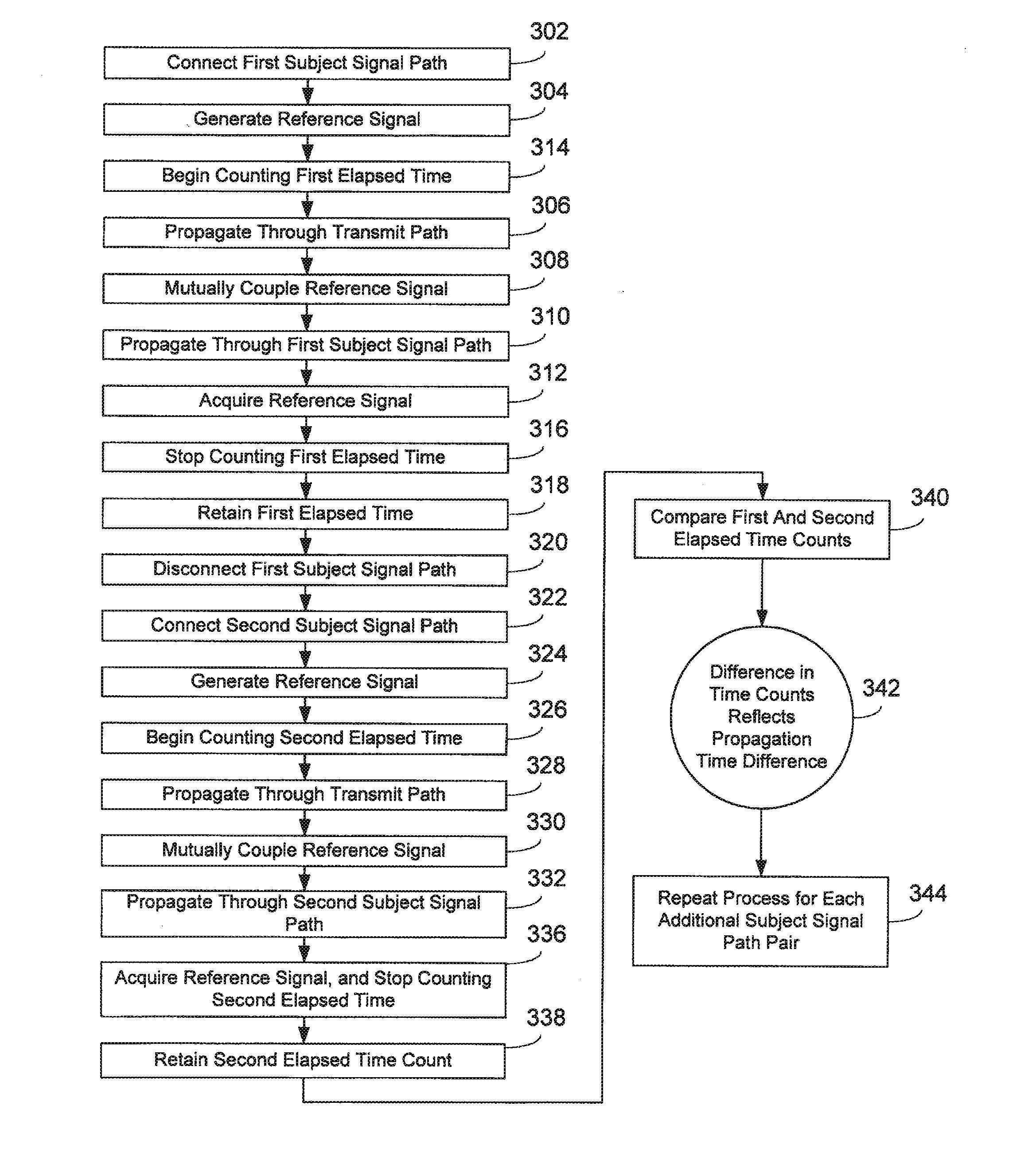
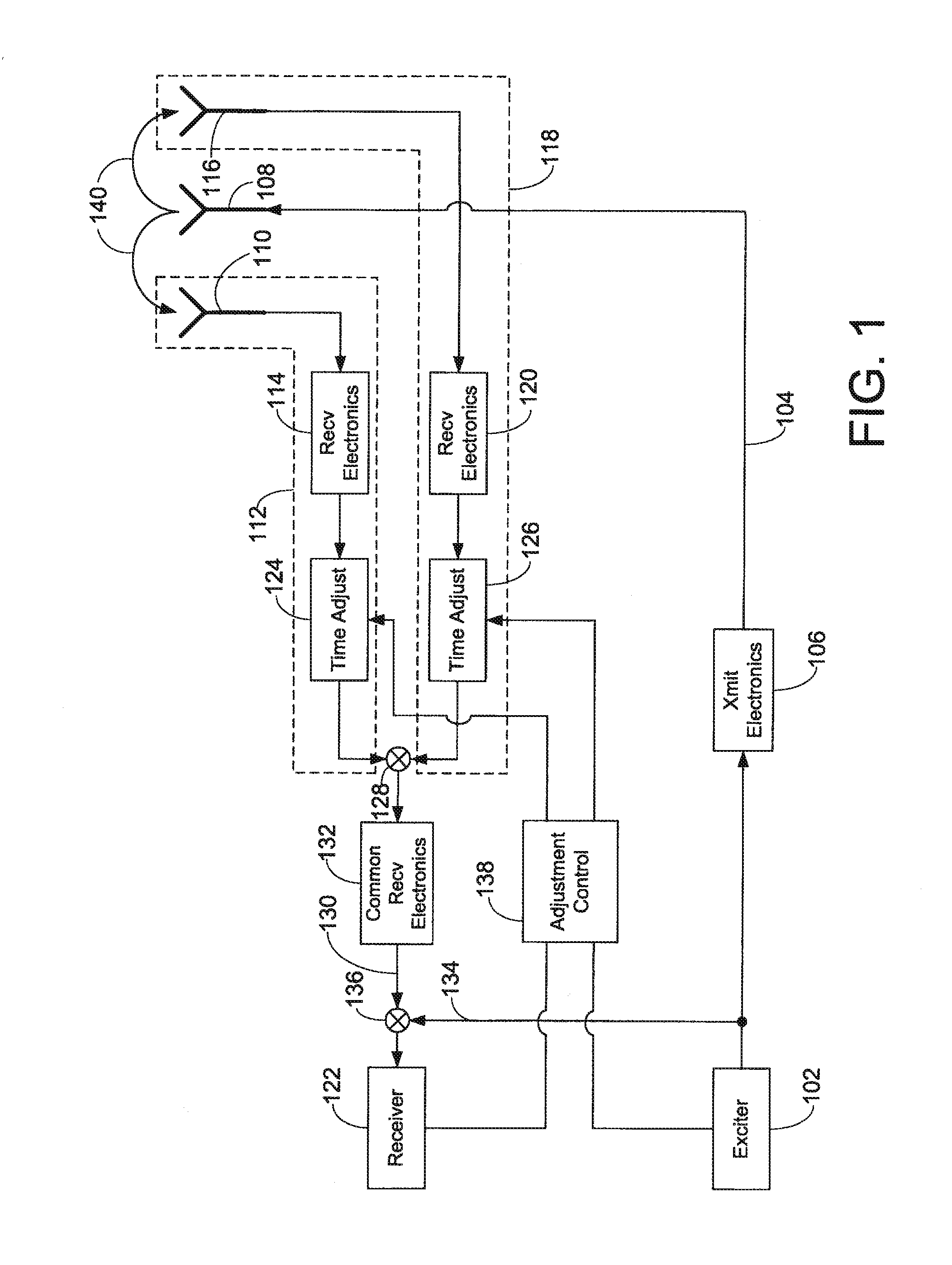
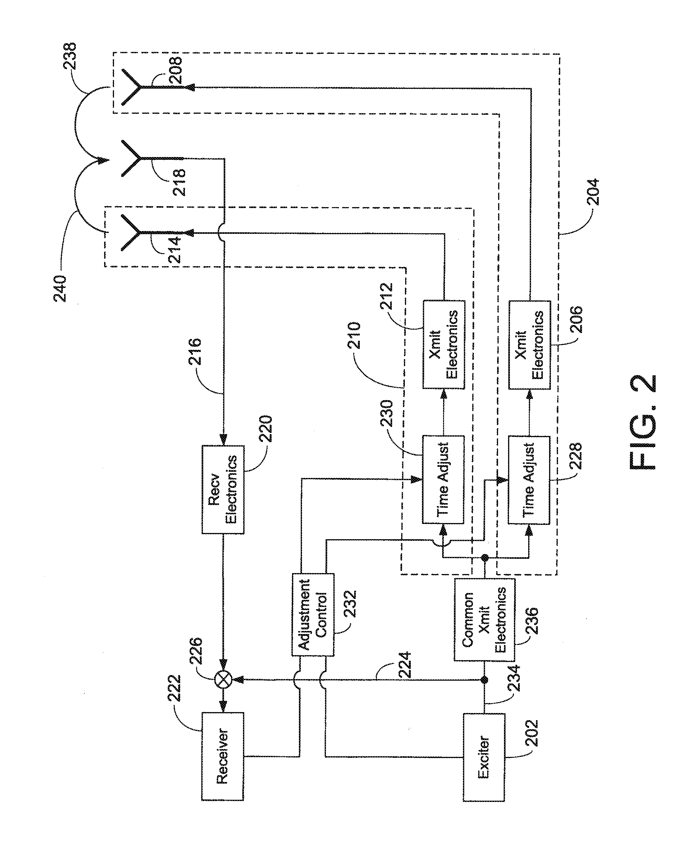
[0028]Embodiments in accord with the present invention are directed to a method and system for a radio frequency transmit / receive system that employs a selected reference signal and takes advantage of the mutual coupling property of multiple antenna elements to determine aspects of propagation time of a signal through multiple parallel signal paths, here called “subject signal paths,” that are also traversed by an operational signal between its generation and its reception during normal operation of the system. The generation of the reference signal and the acquisition of either the reference signal or signals derived from mixing instances of the reference signal are performed by the same exciter and receiver as are used for normal operational, permitting the aspects of signal path propagation time to be determined without the need for dedicated external measurement equipment.

[0029]Embodiments in accord with the present invention display reciprocity, that is, the methods of measurem...


PUM


Abstract

A method and system use the mutual coupling property of multiple antenna elements for measuring differences in propagation time among various signal paths involving antenna elements in a radio frequency transmit / receive system. The method and system alleviate the need for external test equipment by using the same hardware used in standard operation of the transmit / receive system for performing propagation time measurement through the generation, mutual coupling, and acquisition of a specially selected reference signal. In an embodiment involving calibration of various signal paths to realize matched propagation times, the signal energy returned through these various paths during standard system operation arrives for acquisition more closely coincident in time, increasing the instantaneous bandwidth of the system.

Description

BACKGROUND OF THE INVENTION[0001]Emerging applications for radio frequency transmit / receive systems are demanding increased instantaneous bandwidth. Such applications include high-data-rate communications, low-probability-of-detection communications, simultaneous occupancy of radio frequency spectrum by multiple users, high-resolution imaging radar, low-probability-of-detection radar, wide-bandwidth electronic signals surveillance, and wide-bandwidth jamming of signals. In all these applications, it is essential for energy from the entire desired spectrum bandwidth to arrive at the receiver. In systems featuring multiple antenna elements associated with multiple signal paths in parallel, maximal energy transfer requires that the signals propagating through these multiple paths arrive at the receiver simultaneously, or as near simultaneously as possible. This does not necessarily occur naturally in a system, because various signal paths associated with various antenna elements may fe...

Claims


Application Information

Patent Timeline
Patent Type & Authority Applications(United States)
IPC IPC(8): H04W24/00
CPCG01S7/4017
Inventor BOE, ERIC N.LEWIS, WILLIAM L.FRASCHILLA, JOHN
Owner RAYTHEON CO
Why Eureka
Try Eureka