Inversion inductor

An integrated technology of inverter inductance, applied in the direction of transformer/inductor magnetic core, etc., can solve the problems of low production efficiency, high cost, large inductance noise, etc., and achieve the effect of simplifying assembly operation, improving production efficiency, and improving quality factor

Inactive Publication Date: 2012-03-14
SHENZHEN CLICK TECH
View PDF3 Cites 4 Cited by
  • Summary
  • Abstract
  • Description
  • Claims
  • Application Information

AI Technical Summary

Problems solved by technology

[0008] Improving the Q value of the inverter inductor has always been the goal pursued by the industry, but it is still not possible to obtain an inverter inductor with a higher Q value
[0009] Secondly, the magnetic core adopts amorphous iron core, which is costl...

Method used


Image

  • Inversion inductor
  • Inversion inductor
  • Inversion inductor

Examples


Embodiment Construction

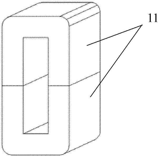
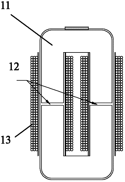
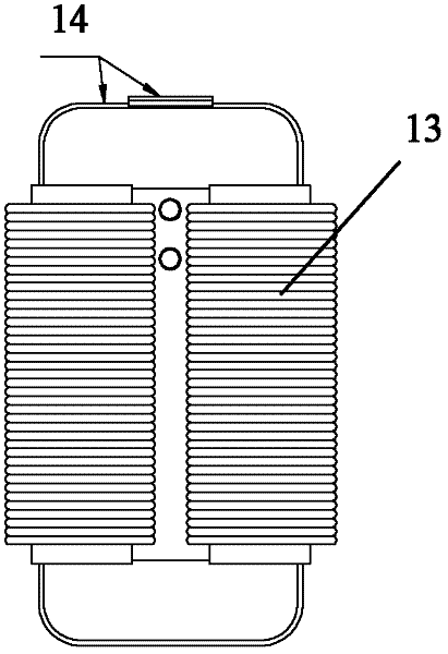
[0043] like Figure 6 to Figure 12 As shown, the inverter inductor of the present invention includes a magnetic core, a coil 25 wound on the magnetic core and a coil lead end 25 .

[0044] The magnetic core includes two plate-shaped magnetic cores 21 and two columnar magnetic cores 22, the two plate-shaped magnetic cores 21 are arranged at intervals relative to each other, and the two columnar magnetic cores 22 are vertically spaced between the two plate-shaped magnetic cores 21, The two ends of the two columnar magnetic cores 22 are docked with the opposite surfaces of the two plate-shaped magnetic cores 21 respectively, the two plate-shaped magnetic cores 21 and the two columnar magnetic cores 22 are connected as one, and the coils 25 are respectively wound on the two columnar magnetic cores. on core 22.

[0045] In this embodiment, the two plate magnetic cores 21 adopt a cuboid structure. In other embodiments, the two plate magnetic cores 21 may adopt other structural sha...


PUM


Abstract

The invention discloses an inversion inductor, which comprises a magnetic core, and a coil and a coil leading-out terminal wound on the magnetic core, wherein the magnetic core comprises a plate-shaped magnetic core A, a plate-shaped magnetic core B, a column-shaped magnetic core A, and a column-shaped magnetic core B; the plate-shaped magnetic core A and the plate-shaped magnetic core B are arranged in a relatively spacing manner, the column-shaped magnetic core A and the column-shaped magnetic core B are vertically arranged between the plate-shaped magnetic core A and the plate-shaped magnetic core B in a spacing manner, and both ends of the column-shaped magnetic core A and both ends of the column-shaped magnetic core B are respectively in abutment joint with the opposite surfaces of the plate-shaped magnetic core A and the plate-shaped magnetic core B, so that the plate-shaped magnetic core A, the plate-shaped magnetic core B, the column-shaped magnetic core A, and the column-shaped magnetic core B are connected into an integral whole; and the coil is wound on the column-shaped magnetic core A and the column-shaped magnetic core B respectively. By using the inversion inductor disclosed by the invention, the quality factor of the inversion inductor is improved, the material cost of the magnetic core is greatly reduced, noise and heat generation are decreased, and at the same time, the operation of assembly is greatly simplified, thereby being beneficial to improving the production efficiency of the inversion inductor.

Description

technical field [0001] The invention relates to an inverter inductor. Background technique [0002] The inverter inductor is an important part widely used in the inverter, and its performance has a great influence on the overall performance of the inverter. [0003] like Figure 1 to Figure 5 As shown, the magnetic cores of the existing inverter inductors generally use two U-shaped amorphous structure iron cores 11 arranged opposite to each other in the middle, and the two iron cores 11 are bound and fixed with iron bands 14. The straight part of 11 is wound around the coil 13, leading out the coil lead-out 15. Structurally, an air gap 12 must be provided between the opposite ends of the two iron cores 11 to meet the inductance requirement. [0004] The existing inverter inductance has the following defects: [0005] First of all, because there is an air gap 12 in the middle junction of the two magnetic cores of the existing inverter inductor, the magnetic core must be bo...

Claims


Application Information

Patent Timeline
IPC IPC(8): H01F27/26H01F27/24
Inventor 肖铿周正国曾海峰陈义辉贺长万
Owner SHENZHEN CLICK TECH
Why Eureka
Try Eureka