Smartfold electronic actuation

a technology of electronic actuation and smartfolding, which is applied in the direction of movable seats, generators/motors, furniture parts, etc., can solve the problems of large use of large motors, large space occupation, and complicated motors

Inactive Publication Date: 2010-08-17
LEAR CORP
View PDF34 Cites 13 Cited by
  • Summary
  • Abstract
  • Description
  • Claims
  • Application Information

AI Technical Summary

Benefits of technology

[0009]In at least another embodiment, a seat assembly for use with an automotive vehicle is provided. The seat assembly may have a seat bottom, a seat back that is rotatably connected to the seat bottom, and a latch assembly that may be connected to the seat back. The latch assembly may be moveable between a locked position and a release position. The seat back may be inhibited from rotating where the latch assembly is in the locked position and the seat back may be free to rotate while the latch assembly is release position. The seat assembly further includes an actuator assembly that is associated with a latch assembly. The actuator assembly may have a plurality of components configured for movement, a release mechanism that may be configured for rotation between a hold position and a release position to control the movement of the plurality of components, and a shape memory alloy wire associated with the release mechanism. The shape memory alloy wire may contract in length when electrified and may be confined to contract along a path such as, when contracting, the shape memory alloy wire torques the release mechanism thereby causing the release mechanism to rotate from the hold position to the release position.

Problems solved by technology

Existing remotely actuated actuators require the use of relatively large, complicated motors that are bulky and that use a substantial amount of space.

Method used


Image

  • Smartfold electronic actuation
  • Smartfold electronic actuation
  • Smartfold electronic actuation

Examples


Embodiment Construction

)

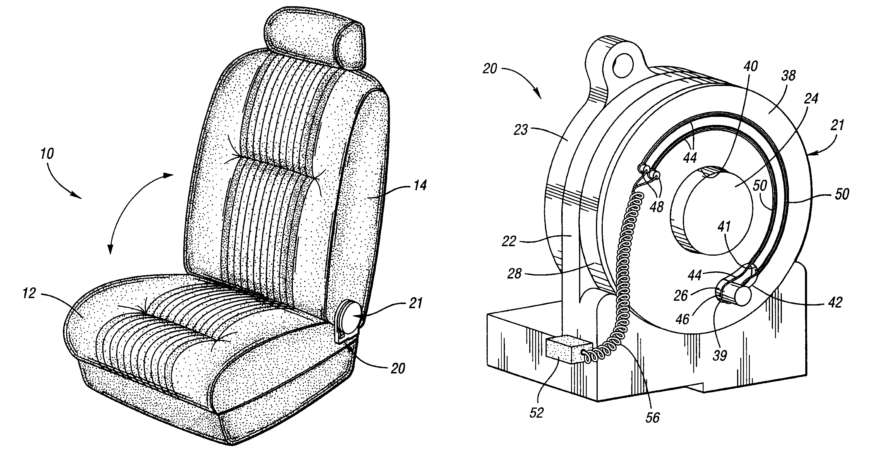
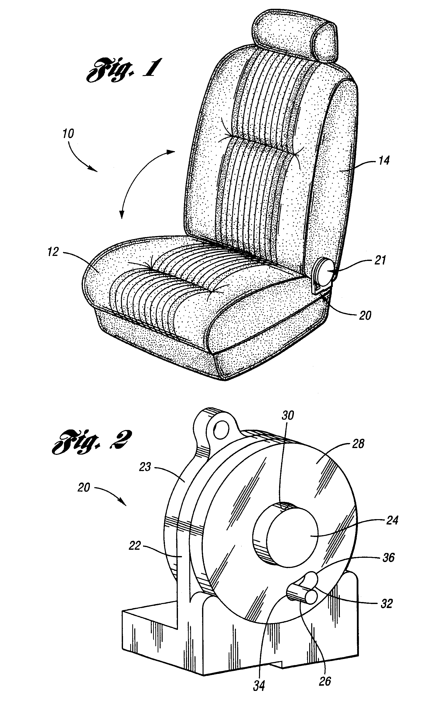
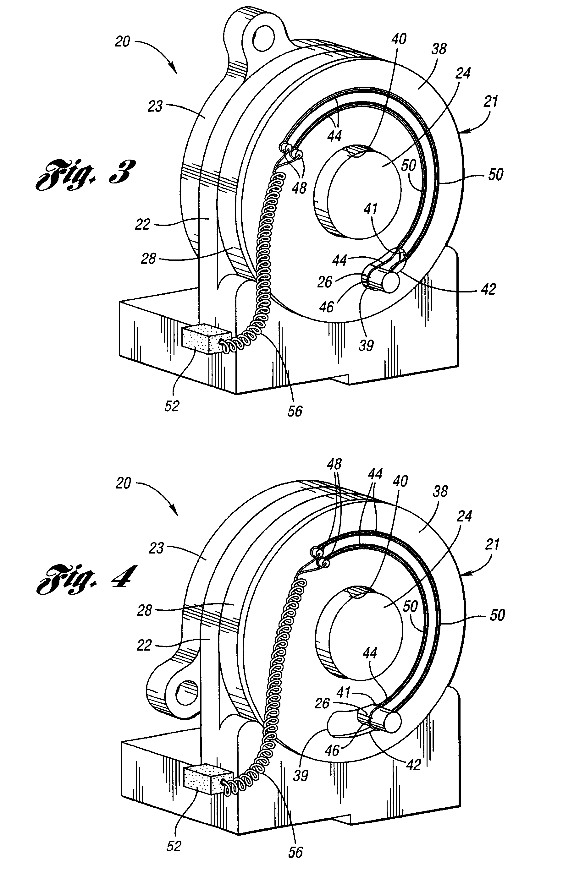
[0019]Reference will now be made in detail to the illustrated embodiments of the present invention which constitute the best modes of practicing the invention presently known to the inventors. The following descriptions are merely exemplary in nature and in no way intended to limit the invention, its application, or uses. The figures are not necessarily drawn to scale. Specific details disclosed herein are not to be interpreted as limiting, but merely as a representative basis for any aspect of the invention and / or as a representative basis for teaching one skilled in the art to variously employ the present invention.

[0020]Shape memory alloys are materials that are known to contract when heated. Shape memory alloys return to their original shape after they have been heated to a temperature above a threshold temperature. Persons skilled in the art are aware of numerous metal alloys such as TiNiPd, TiNi, CuAl, CuZnAl, or CuAlNi, which have these properties. When shape memory alloy me...


PUM


Abstract

An electronic trigger assembly for triggering an actuator, the electronic trigger assembly having a trigger member capable of connection to the actuator. The trigger member may be configured for rotation between a first position and a second position and the trigger member may be able to trigger the actuator as the trigger member rotates between the first position and the second position. The trigger member may also include a guide. A shape memory alloy member may be connected to the trigger member and may be received by the guide such that a substantial portion of the shape memory alloy member is disposed in a curvilinear arrangement. The shape memory alloy member may contract when electrified. The shape memory alloy member may be confined by the guide to contract along a path such that the shape memory alloy member exerts torque on the trigger member and causes the trigger member to rotate from the first position to the second position.

Description

BACKGROUND OF THE INVENTION[0001]1. Field of the Invention[0002]The present invention relates to remotely actuated vehicle seats.[0003]2. Background Art[0004]Latches are frequently used to secure a vehicle seat back in a particular orientation, such as an upright position, with respect to a seat bottom. When the latch is released, the seat back is free to rotate with respect to the seat bottom. In other applications, the seat back and the seat bottom may move with respect to one another in ways other than rotation, such as translation. Latches may be used to restrict this motion as well.[0005]Actuators are devices that can trigger the operation of an apparatus. For instance, an actuator may be used to release a latch. Some actuators may be remotely triggered and, if coupled to a latch, may permit an operator to release the latch from a distance. When an actuator engages a latch on a vehicle seat, the actuator can trigger the motion of the seat. If the actuator is configured for remo...

Claims


Application Information

Patent Timeline
Patent Type & Authority Patents(United States)
IPC IPC(8): B60N2/22B60N2/90
CPCB60N2/20
Inventor KENNEDY, KARL R.NATHAN, JOHN F.HANLON, SAMUEL R.MAUE, H. WINSTON
Owner LEAR CORP
Why Eureka
Try Eureka