Kick-in resistant door reinforcing assembly

a technology of resisting door and reinforcement assembly, which is applied in the direction of building locks, constructions, fastening means, etc., can solve the problem of lateral movement of the vertical door jamb

Inactive Publication Date: 2008-04-22
JOEL ASSOC L L C
View PDF44 Cites 15 Cited by
  • Summary
  • Abstract
  • Description
  • Claims
  • Application Information

AI Technical Summary

Benefits of technology

[0011]Accordingly, an object of the instant invention is the provision of a kick-in resistant door reinforcing assembly which effectively transfers kick forces from a door to a doorway's structurally solid door buck and which incorporates paired door buck and door jamb engaging members incorporating interconnecting means adapted for allowing lateral travel of such members in accordance with lateral traveling motions of a door jamb with respect to a door buck during a door installation process.

Problems solved by technology

Such wedge shimming alignment process commonly causes slight lateral movements of the vertical door jambs with respect to the doorway's bordering door buck members.

Method used


Image

  • Kick-in resistant door reinforcing assembly
  • Kick-in resistant door reinforcing assembly
  • Kick-in resistant door reinforcing assembly

Examples


Embodiment Construction

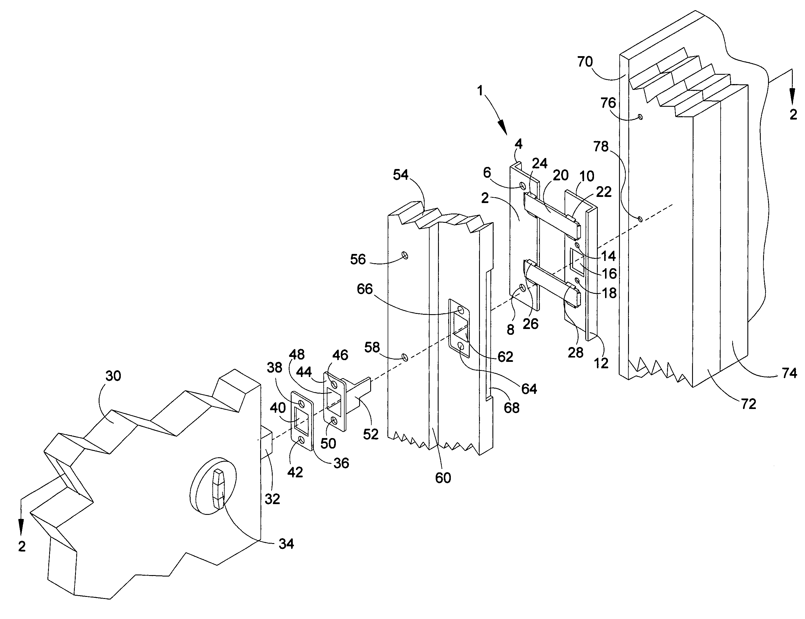
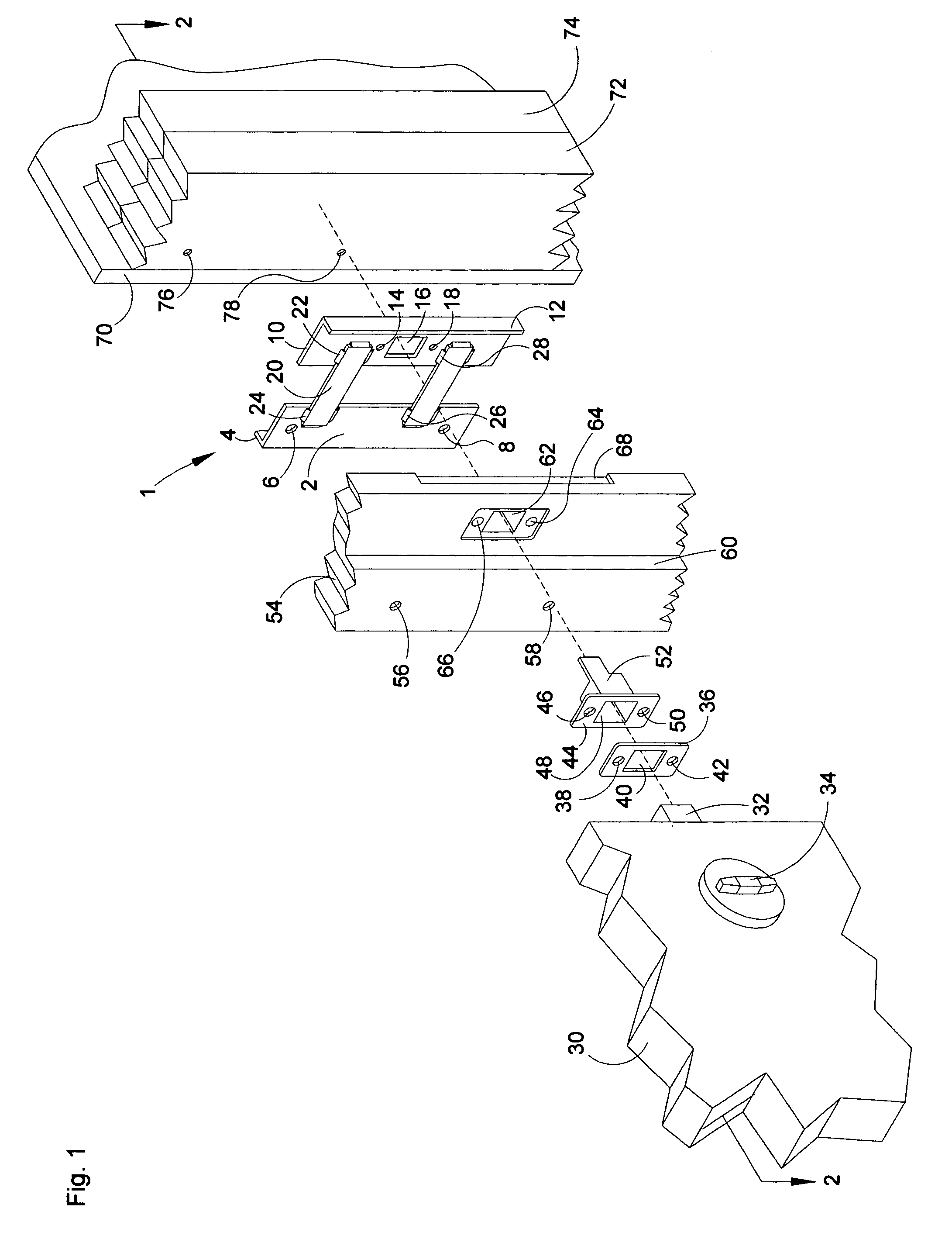
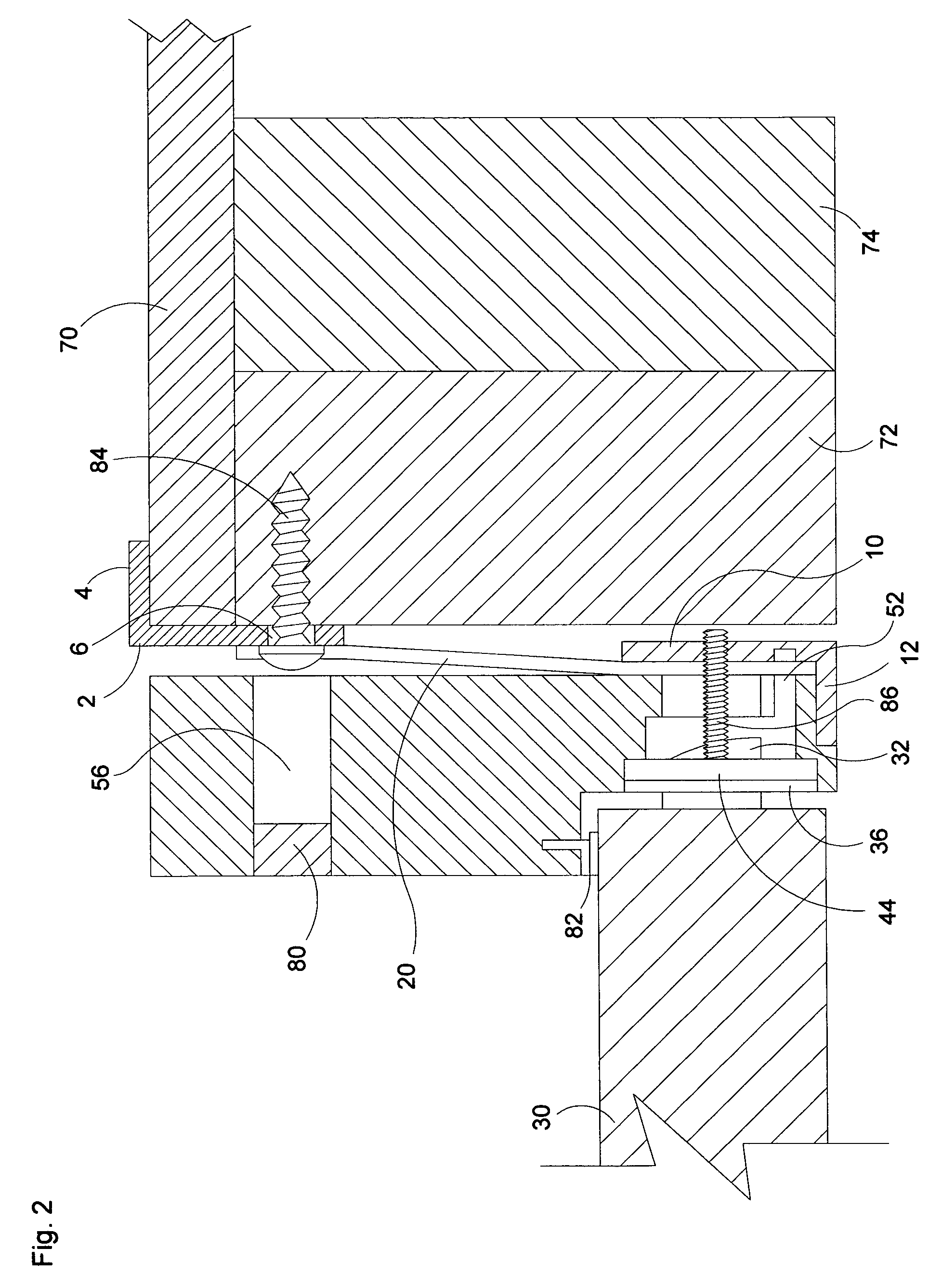
[0016]Referring now to the drawings, and in particular to FIG. 1, a preferred embodiment of the instant inventive kick-in resistant door reinforcing assembly is referred to generally by Reference Arrow 1. The assembly 1 preferably comprises a first doorway or door buck engaging “L” beam which preferably comprises a web 2 which is formed wholly with a laterally outwardly extending foot or hook 4, the web portion 2 preferably having upper and lower screw receiving apertures 6 and 8. Such hooking portion 4 preferably lockingly engages a door buck 72 and 74, preferably via the outer surface of a building's exterior sheathing 70. Suitably, the foot / hook 4 may be mortised into the outer surface of sheathing 70 or, for longitudinal fitting purposes, may alternately extend into a vertical slot (not depicted) within sheathing 70 or within door buck 72. Suitably, though less desirably, the hook or foot portion 4 may be omitted and the requisite doorway engaging member may alternately exclusiv...


PUM


Abstract

A kick-in resistant door reinforcing assembly consisting of a doorway hook having a laterally outwardly extending doorway engaging face; a jamb hook having a laterally inwardly extending jamb engaging face; and at least a first hook interconnecting flexible band spanning between the doorway and jamb hooks, the hook interconnecting flexible band being adapted for permitting alternate laterally inward and outward movements of the doorway and jamb hooks with respect to each other.

Description

FIELD OF THE INVENTION[0001]This relates to home security apparatus and assemblies. More particularly, this invention relates to assemblies adapted for protecting residential or commercial building exterior doorways from forced entries resulting from applications of percussive forces to door exteriors.BACKGROUND OF THE INVENTION[0002]Residential and commercial buildings are commonly burglarized via unauthorized forced entry. Commonly, burglars who gain entry to a targeted residence or commercial building do so by applying a forceful flat-footed kick to the exterior of an entry door at a location near the door's hasp or bolt. Very commonly such kicking pressure causes the door's bolt to tear or break inwardly through the door's casing or vertical jamb which laterally borders the door and which includes an aperture for receiving the bolt. Upon such breakage of a door jamb, the door freely swings inwardly, allowing a burglar to access the interior of the building.[0003]Various doorway ...

Claims


Application Information

Patent Timeline
Patent Type & Authority Patents(United States)
IPC IPC(8): E05B15/02E05B17/00
CPCE05B15/0205E05B17/2088E06B7/28Y10T292/68Y10T292/694Y10T292/79
Inventor POSTON, KEVIN D.
Owner JOEL ASSOC L L C
Why Eureka
Try Eureka