Electrical device with lamp module

a technology of electrical devices and lamps, applied in the direction of coupling device connections, tumbler/rocker switches, lighting and heating apparatus, etc., can solve the problems of increasing the cost of electrical installation, not being reconfigurable from a non-illuminated device, and hazardous searching for those involved

Active Publication Date: 2008-04-22
PASS SEYMOUR
View PDF8 Cites 89 Cited by
  • Summary
  • Abstract
  • Description
  • Claims
  • Application Information

AI Technical Summary

Benefits of technology

[0008]In another embodiment, the present invention includes a method of installing an electrical wiring device. The method of installing an electrical wiring device includes the step of providing electrical wiring device for use in an electric circuit. The wiring device includes at least one switch disposed within the device housing. The at least one switch includes at least one terminal member configured to be coupled to the electric circuit to thereby energize the electrical device when coupled. The wiring device also includes a lamp receptacle formed in the device housing. The lamp receptacle includes a contact element...

Problems solved by technology

Such searching is hazardous and unsafe for those involved.
One draw back to these devices is that once installed they are not reconfigurable from a non-illuminated device to an illuminated device.
For example, if a wall mounted, non-illuminated electrical wiring device...

Method used


Image

  • Electrical device with lamp module
  • Electrical device with lamp module
  • Electrical device with lamp module

Examples


Embodiment Construction

[0020]Reference will now be made in detail to the present embodiments of the invention, examples of which are illustrated in the accompanying drawings. Whenever possible, the same reference numerals will be used throughout the drawings to refer to the same or like parts.

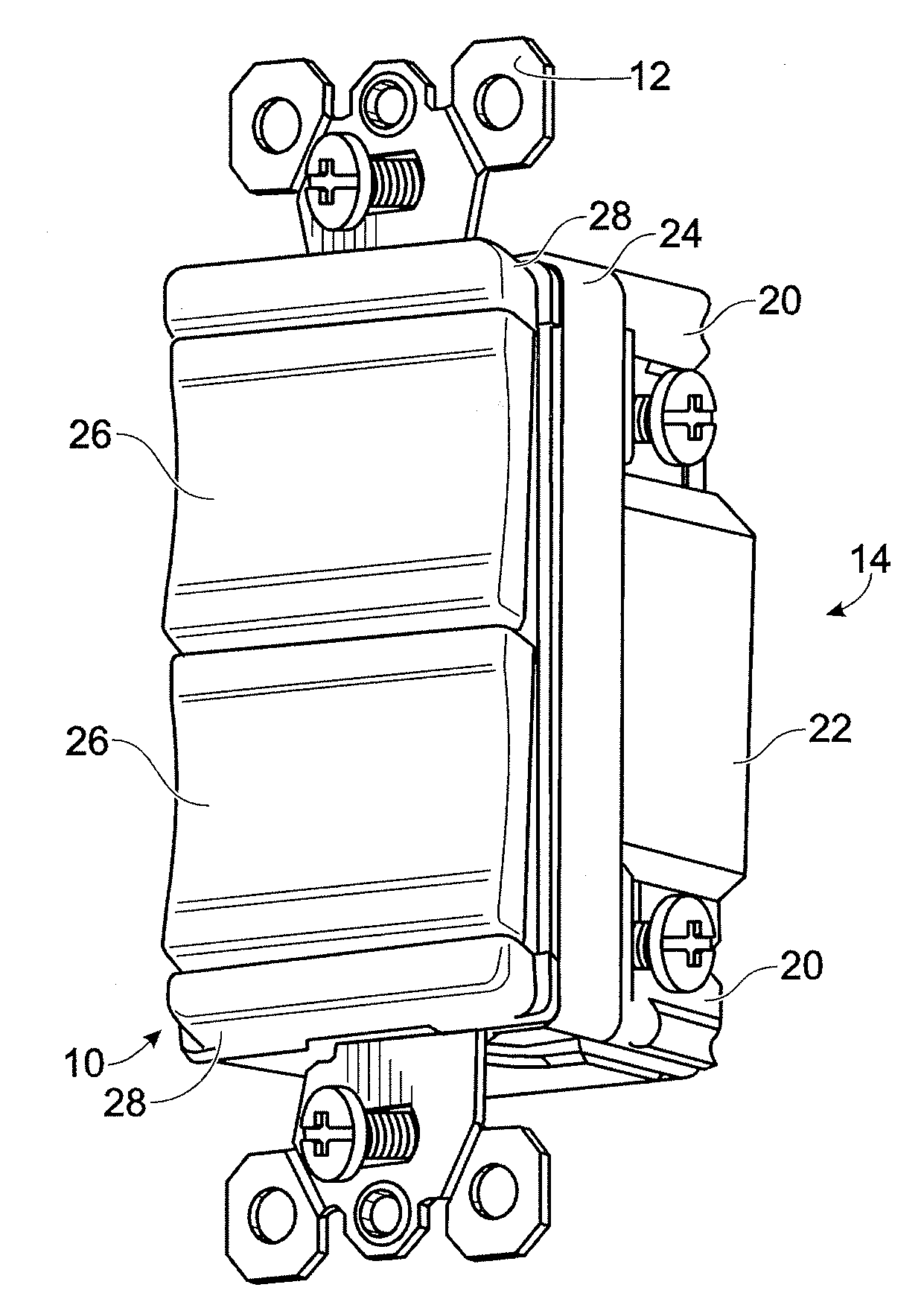
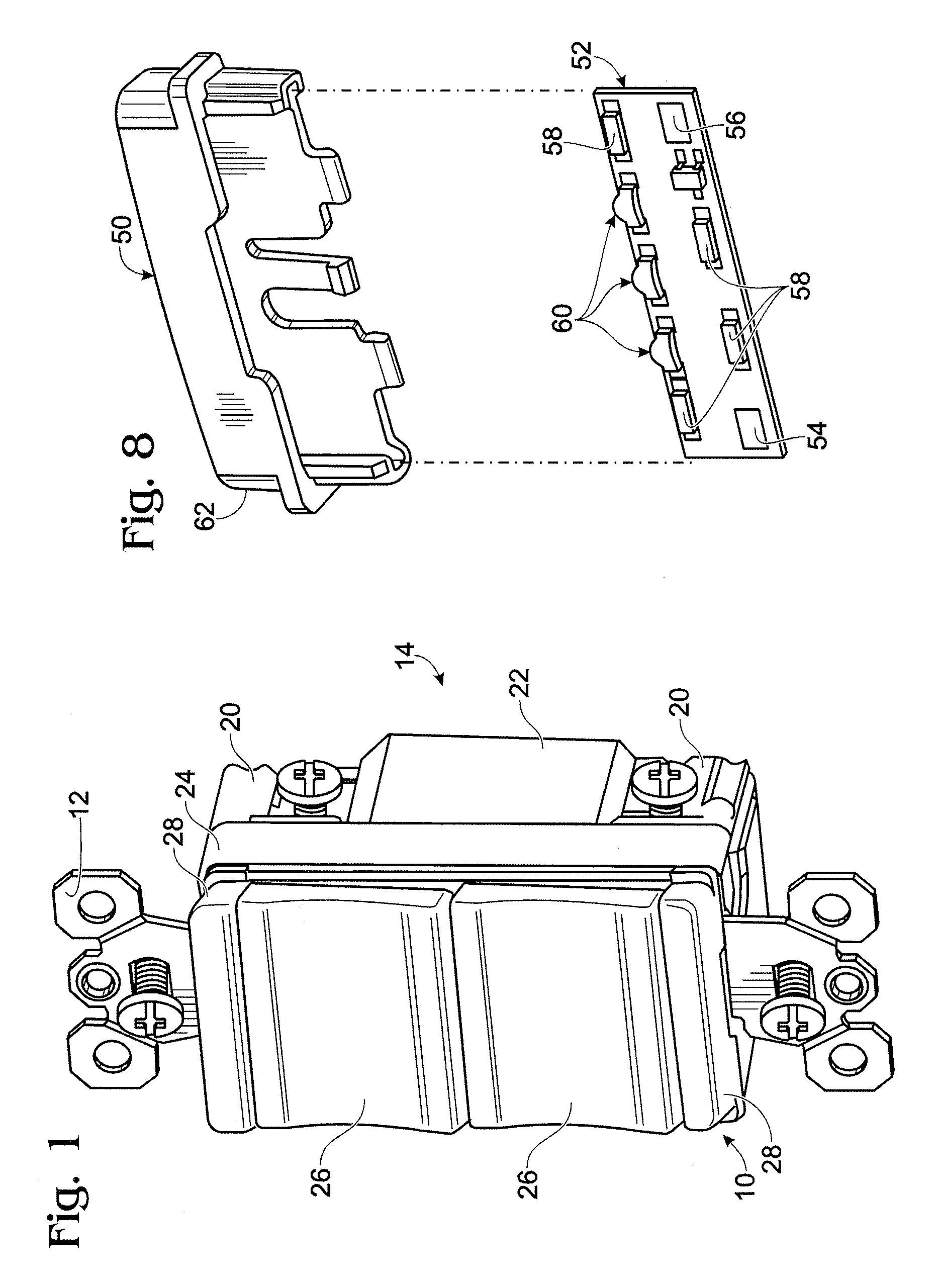
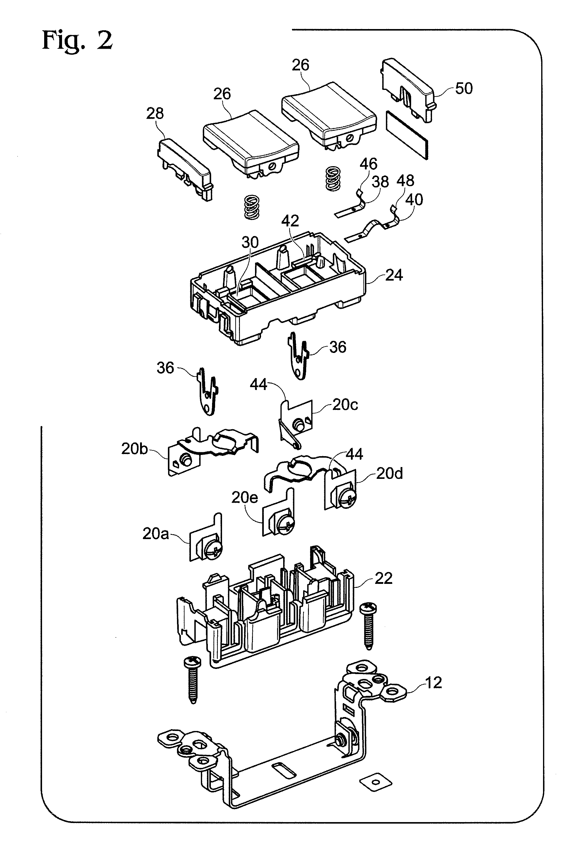
[0021]One embodiment of the electrical device of the present invention is shown in FIG. 1 and is designated generally throughout by the reference numeral 10. The electrical wiring device 10 includes a ground strap 12 and a housing 14. The housing 14 is configured for installation in an electrical wall box. The ground strap 12 is configured to attach the electrical wiring device 10 to the wall box. Typically screws are used to attach the ground strap 12 to the wall box. The housing 14 includes a body 22 and frame 24. Both the body 22 and the frame 24 are made from a non-electrically conductive material, such as, for example plastic and may be made by injection molding, although those skilled in the art of making elect...


PUM


Abstract

An electrical wiring device for use in an electric circuit. The electrical wiring device includes a device housing and at least one switch disposed within the device housing. The at least one switch includes at least one terminal member configured to be coupled to the electric circuit to thereby energize the electrical device when coupled. The electrical wiring device further includes a lamp receptacle formed in the device housing, the lamp receptacle including a contact element that is electrically coupled to the at least one terminal member and a lamp module including a circuit contact member. The lamp module having a lamp module form factor that is configured to be inserted into the lamp receptacle such that the lamp circuit contact member engages the contact element to thereby establish electrical connectivity between the lamp light module and the at least one terminal member, the lamp module also being removable from the lamp receptacle to thereby disengage the circuit contact member from the contact element.

Description

CROSS-REFERENCE TO RELATED APPLICATIONS[0001]This is a continuation of U.S. patent application Ser. No. 10 / 726,173 filed on Dec. 2, 2003 now U.S. Pat. No. 7,213,932 the content of which is relied up and incorporated herein by reference in its entirety, and the benefit of priority under 35 U.S.C. § 120 is hereby claimed.BACKGROUND OF THE INVENTION[0002]1. Field of the Invention[0003]The present invention relates to an electrical wiring device and more particularly to an electrical wiring device suitable for commercial and residential use.[0004]2. Background of the Invention[0005]Upon entering a darkened room a person unfamiliar with the layout of the room must typically locate a wall switch to turn on the lights. Searching for a wall switch in a darkened room often requires navigating around objects such as tables and chairs. Such searching is hazardous and unsafe for those involved. Thus, there is a need for an electrical wiring device that provides a visual indication as to its loc...

Claims


Application Information

Patent Timeline
IPC IPC(8): F21V33/00
CPCH01H23/025H01R13/717H01R13/70H01R24/76H01R2103/00H01H11/0006
Inventor SAVICKI, JR., GERALD R.
Owner PASS SEYMOUR
Why Eureka
Try Eureka