Airless accumulation conveyor

a conveyor and airless technology, applied in the direction of conveyor parts, roller-ways, transportation and packaging, etc., can solve the problems of less than optimal system operation, additional expense for pneumatic supply system installation, maintenance and operation of compressors, etc., and achieve the effect of reducing maintenance over pneumatic systems

Inactive Publication Date: 2008-04-29
DEMATIC
View PDF42 Cites 10 Cited by
  • Summary
  • Abstract
  • Description
  • Claims
  • Application Information

AI Technical Summary

Benefits of technology

[0004]The present invention is directed to an accumulation conveyor that does not utilize pneumatic activation. In particular, the present invention is directed to an all-electric accumulation conveyor. Because it is all-electric, there is no necessity to operate a compressor system needed to supply pneumatic energy which must be operated irrespective of the load on the conveyor system. Also, the present invention is expected to have reduced maintenance over pneumatic systems.
[0007]An electromagnetic actuator may be provided in the vertical plane and causing the force transmission member to transmit force between the concentric cylinders when the electromagnetic actuator is actuated. The electromagnetic actuator may be generally stationary. This advantageously facilitates the wiring to the electromagnetic actuator without the necessity of slip-rings, and the like. This reduces the cost of any potential maintenance difficulties with the accumulation conveyor.

Problems solved by technology

While pneumatic actuation is very effective, it requires additional expense for installation of a pneumatic supply system as well as the cost of maintaining and operating a compressor.
Also, plastic tubing used in the system may leak resulting in less than optimal operation of the system.

Method used


Image

  • Airless accumulation conveyor
  • Airless accumulation conveyor
  • Airless accumulation conveyor

Examples


Embodiment Construction

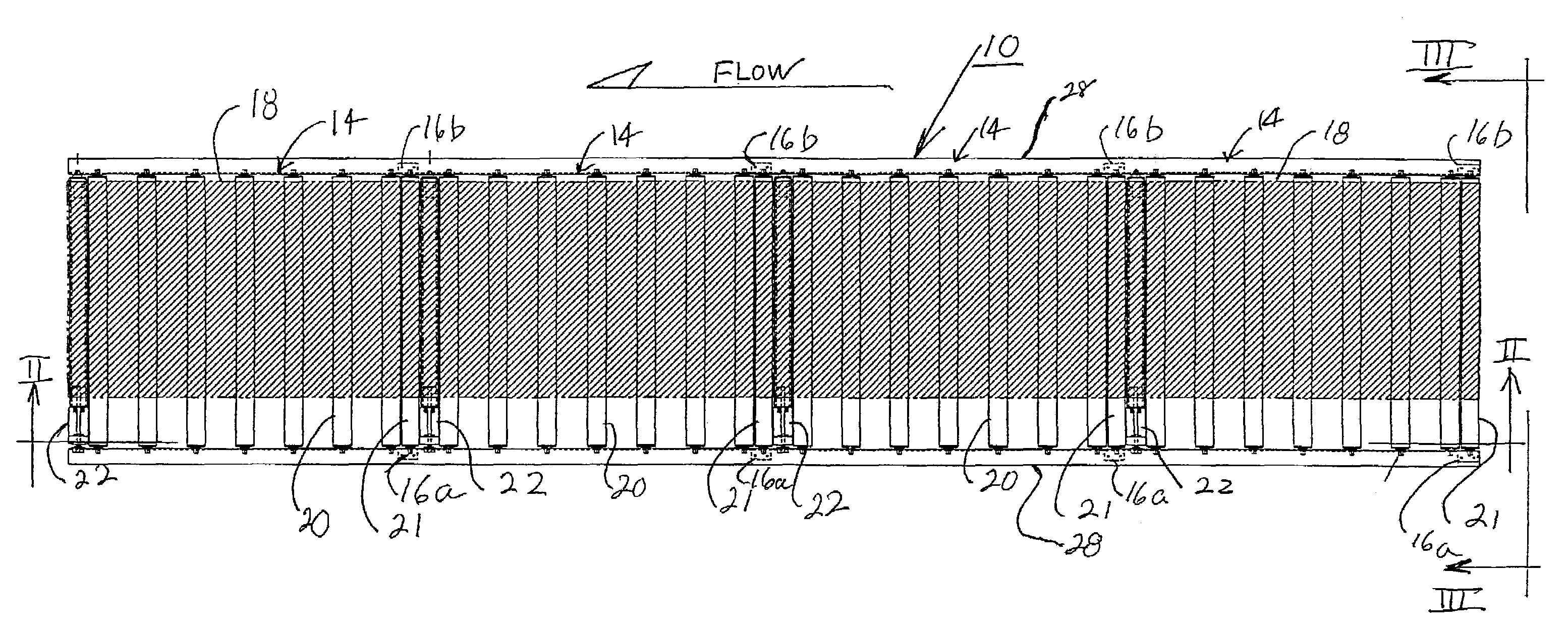
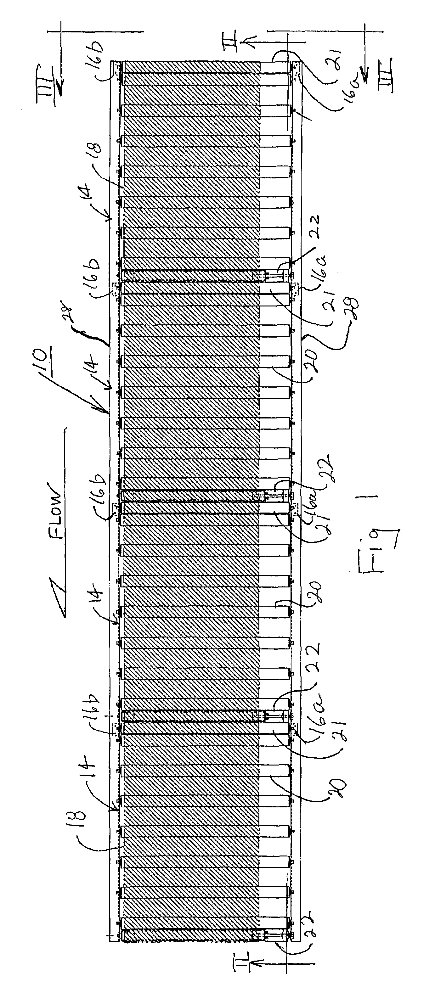
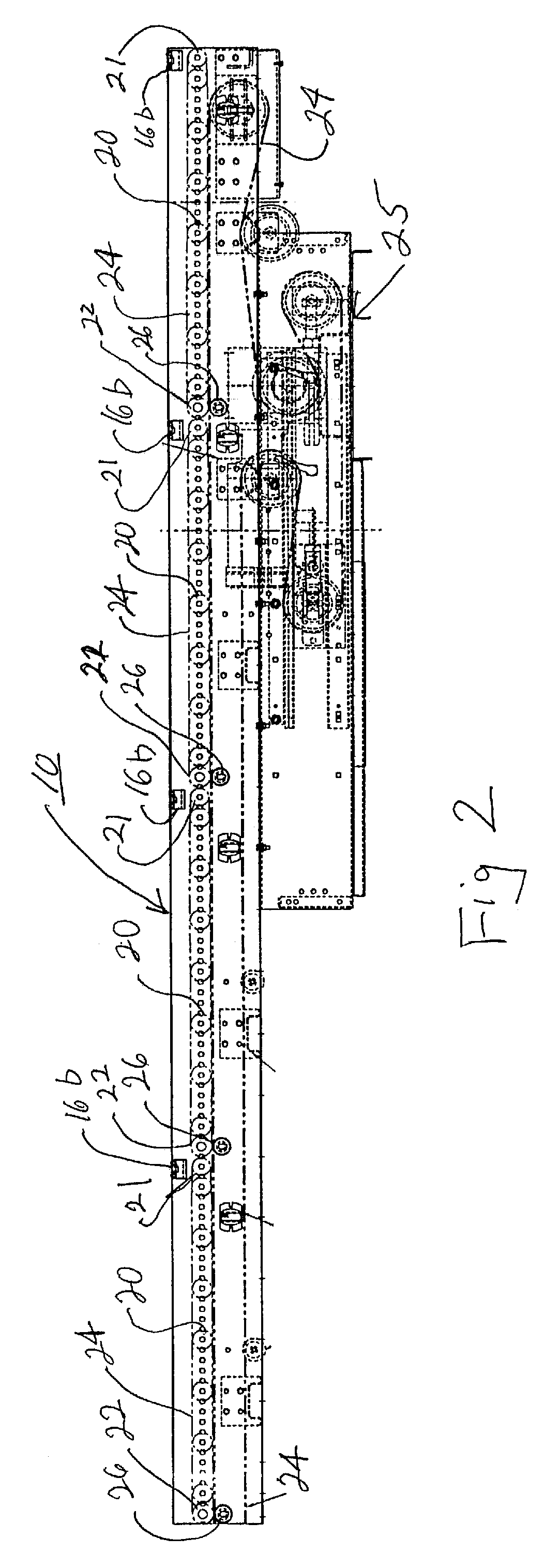
[0026]Referring now specifically to the drawings, and the illustrative embodiments depicted therein, an airless accumulation conveyor 10 includes a conveying surface 12 for conveying articles (not shown). As is conventional, accumulation conveyor 10 is divided into a plurality of tandem zones 14. Each zone includes an article sensor, such as a photo-eye, for sensing articles in the particular zone. In the illustrated embodiment, the photo-eye uses a source / sensor unit 16a and a reflector 16b, but unitary sensors may be used. Also, proximity sensors, sensing rollers, and the like, may be used. Each zone further includes a conveying belt 118 that is selectively movable to convey articles and stopped to accumulate articles. Accumulation conveyor 10 may be controlled by any of various known accumulation control techniques. It may be controlled using the techniques disclosed in commonly assigned application Ser. No. 60 / 597,178 filed by Lupton entitled ARTICLE ACCUMULATION METHOD AND APPA...


PUM


Abstract

An accumulation conveyor and method, according to the invention, includes providing a plurality of tandem accumulation zones, each of the zones including a conveying surface and at least one drive roller selectively driving the conveying surface. A drive member below the conveying surface extends a length of the plurality of tandem accumulation zones. Each of the zones includes a clutch roller rotated by the drive member and an electromagnetic clutch. The clutch selectively transfers rotation of the clutch roller to the drive roller to drive the conveying surface. The clutch may be made up of a pair of concentric cylinders aligned in a vertical plane and a force transmission member between the concentric cylinders with the force transmission member transmitting force between the concentric cylinders when the clutch is electrically actuated. The clutch may be a wrapped-spring clutch.

Description

CROSS REFERENCE TO RELATED APPLICATIONS[0001]This application claims priority from U.S. provisional patent application Ser. No. 60 / 684,378, filed on May 25, 2005; U.S. provisional patent application Ser. No. 60 / 714,931, filed on Sep. 7, 2005; U.S. provisional patent application Ser. No. 60 / 597,503, filed on Dec. 6, 2005; and U.S. provisional patent application 60 / 766,346, filed on Jan. 12, 2006, the disclosures of which are hereby incorporated herein by reference in their entirety.BACKGROUND OF THE INVENTION[0002]The present invention is directed to an accumulation conveyor system and, in particular, to such a system utilizing a conveying surface driven by rollers and an elongated drive member which selectively rotates the rollers. The drive member is illustrated as an endless drive belt. However, other drive members, such as shafts, may be used.[0003]It is known to provide accumulation conveyors utilizing pneumatic actuation. While pneumatic actuation is very effective, it requires...

Claims


Application Information

Patent Timeline
Patent Type & Authority Patents(United States)
IPC IPC(8): B65G13/06
CPCB65G13/07B65G13/071B65G13/073B65G47/261
Inventor GERMAN, HARRY TCOTTER, DAVID HPELAK, WYNN MSCHUITEMA, DENNIS J
Owner DEMATIC
Why Eureka
Try Eureka