Rear projection image display apparatus

a technology of display apparatus and rear projection, which is applied in the field of rear projection image display apparatus, can solve the problems of difficulty in its manufacture, difficulty in ensuring the positional accuracy of each lens, and the magnification of the disclosed afocal converter is too low to permit a wide view angle, so as to increase the compactness of the set and the effect of compact apparatus

Inactive Publication Date: 2008-04-29
HITACHI LTD
View PDF10 Cites 2 Cited by
  • Summary
  • Abstract
  • Description
  • Claims
  • Application Information

AI Technical Summary

Benefits of technology

[0008]The present invention has been made in view of the above problems and provides a technique which contributes to the compactness of the set.
[0012]According to another aspect of the invention, an optical path turning means is located between the first lens group and the second lens group and the first lens group is virtually perpendicular to the horizontal direction of the screen surface and the second lens group is virtually perpendicular to the screen surface. This enables an image from the projection lens system to be directly projected on the screen in enlarged form, leading to a more compact apparatus.
[0013]The above structure eliminates the need for a reflection mirror which would be required in a conventional projection image display apparatus. Consequently, the problem of trapezoidal distortion is resolved and a more compact apparatus is realized. Therefore, the present invention increases the compactness of the set.

Problems solved by technology

However, the magnification of the disclosed afocal converter is too low to permit a wide view angle (make the set compact).
In the projection optical system described in literature 2, it is impossible to make the view angle wide enough to realize a sufficiently thin (low-profile) rear projection image display apparatus; therefore, the lenses in use must be decentered individually and thus there is difficulty in its manufacture.
Hence, the problem is that in the manufacturing process, it is not easy to assure positional accuracy of each lens.
In the above prior art, attention has been paid only to the projection optical system including a projection lens but few efforts have been made to optimize the overall system design in consideration of space for drive circuitry in the housing.
Particularly, one problem is that the reflection mirror provided for the sake of the compactness of the set is very sensitive and its positional error might cause image trapezoidal distortion.
The use of the reflection mirror somewhat helps reduce the size of the set but makes it impossible to taper the set from its front side to its back side; as a consequence, when the set is viewed sideways, it does not look thin enough.

Method used


Image

  • Rear projection image display apparatus
  • Rear projection image display apparatus
  • Rear projection image display apparatus

Examples


second embodiment

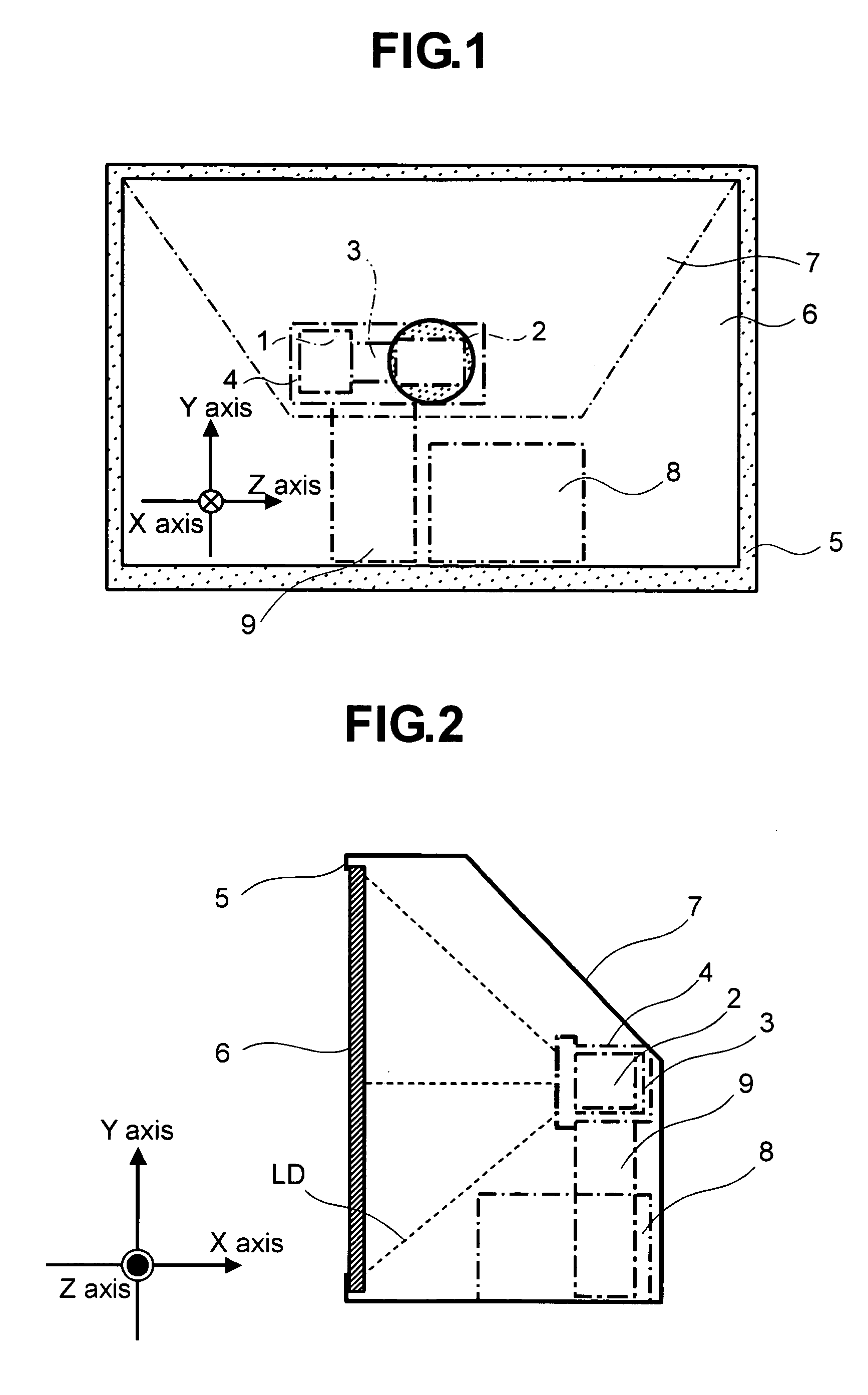
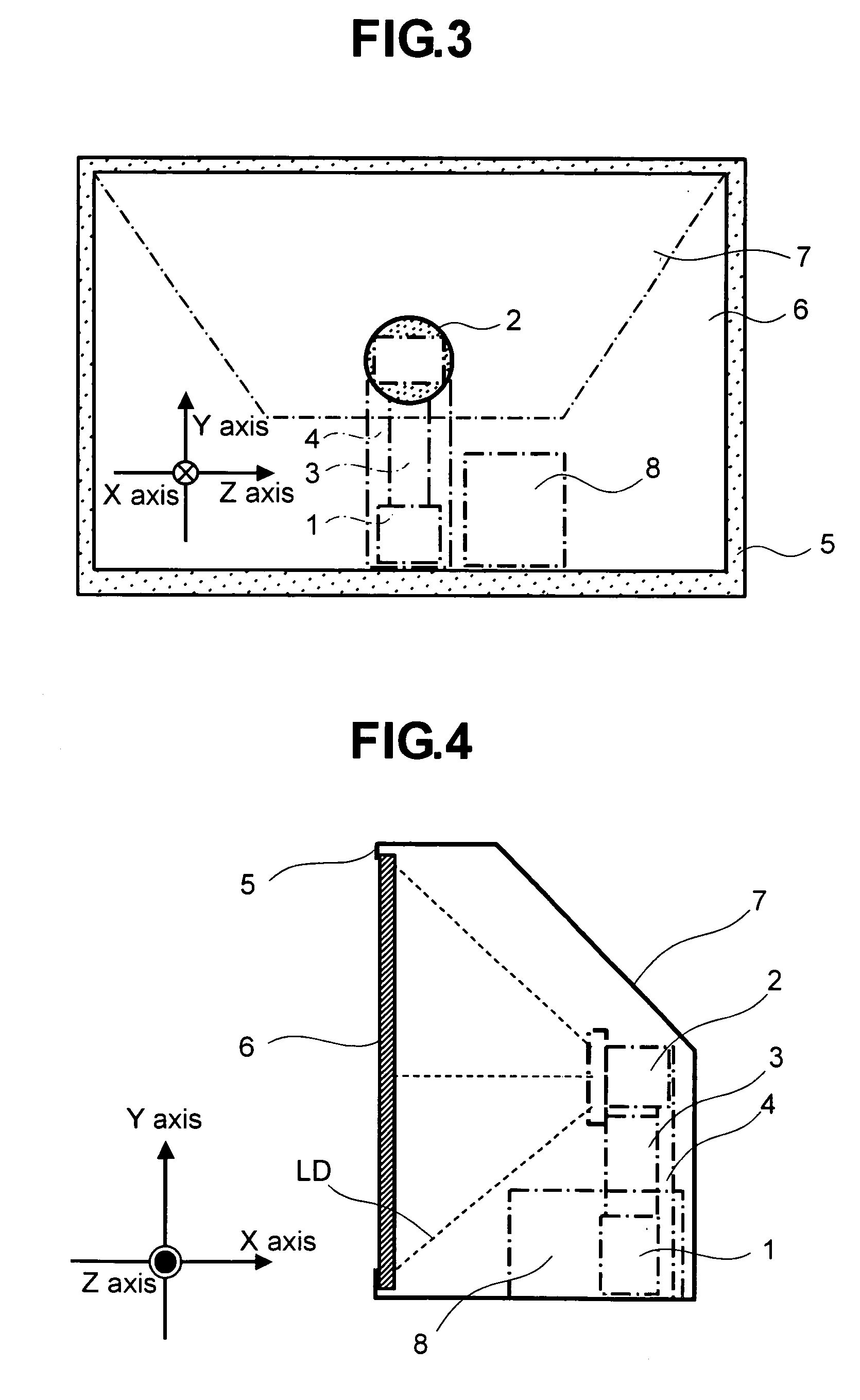
[0068]FIG. 3 is a front view showing a projection optical unit according to the present invention. In the figure, numeral 1 represents an illumination optical system; 5 a housing; 6 a screen; and 7 a back cover. Numeral 4 represents a projection optical unit whereby light from a white light source is cast on an image display device (not shown) by the illumination optical system 1 and an image formed according to an image signal at the image display device is enlarged and projected. Numeral 3 represents a first lens barrel which incorporates a first lens group (not shown, explained later) with positive refractive power of the projection optical unit; 2 a second lens barrel which incorporates a second lens group (not shown, explained later) with positive refractive power of the projection optical unit. Here, a flare stop (marked with hatching) may be provided in an area of the lens nearest to the screen among the lenses built in the second lens barrel other than its effective area (ar...

first embodiment

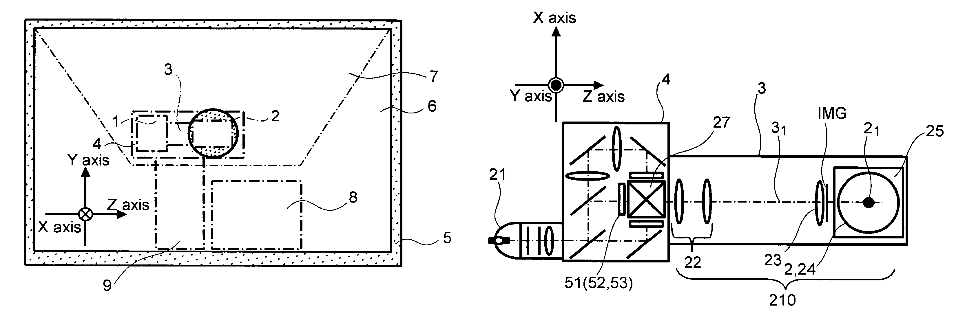
[0074]Details of the projection optical unit in the projection image display apparatus according to the present invention will be described referring to FIG. 5. For convenience of illustration, components with the same functions as those in FIG. 1 are designated by the same reference numerals.

[0075]In the figure, numeral 21 represents a white lamp as a light source; and 4 a transmission liquid crystal panel 51 (52, 53).

[0076]Light from the white lamp 21 is polarized / color-separated by the illumination optical system (not shown) and cast on the transmission liquid crystal panel 51 (52, 53). On the transmission liquid crystal panel 51 (52, 53), the optical intensity of each incoming color light is modulated according to an image signal to make an optical image. These different color optical images are combined by a cross prism 27 to make up a finished color image which is then enlarged by the projection optical unit 210.

[0077]The projection optical unit 210 includes a first lens group...


PUM

PropertyMeasurementUnit
view angleaaaaaaaaaa
sizeaaaaaaaaaa
sizeaaaaaaaaaa

Abstract

A compact rear projection image display apparatus in which the projection distance in a projection optical system is substantially reduced and no reflection mirror is used, thereby eliminating a major cause of image trapezoidal distortion. The rear projection image display apparatus has a projection lens system which includes a first lens group with positive refractive power and a second lens group which further enlarges an image enlarged by the first lens group. The projection lens system enlarges and projects an image displayed on an image display device, on a transmission screen. No reflection mirror is provided between the second lens group and the transmission screen and the image enlarged by the second lens group is directly projected on the transmission screen.

Description

BACKGROUND OF THE INVENTION[0001]1. Field of the Invention[0002]The present invention relates to a rear projection image display apparatus which enlarges and projects an image displayed on an image display device, for example, on a transmission screen through a projection lens system.[0003]2. Description of the Related Art[0004]As an image source for a rear projection image display apparatus (hereinafter sometimes called a “set”), transmission or reflection liquid crystal panels or pixel-selective image display devices such as micromirror devices may be used in place of three CRTs (CRTs which display red, blue and green images). As projection lens systems for the compactness of a set which uses such image display devices, those described in JP-A No. 134213 / 1993 (literature 1), JP-A No. 162544 / 2000 (literature 2) and JP-A No. 357768 / 2002 (literature 3) have been widely known. These patent literature documents disclose projection lens systems which enlarge and project an image on a sc...

Claims


Application Information

Patent Timeline
Patent Type & Authority Patents(United States)
IPC IPC(8): G03B21/22G02B15/14G02B27/10G02B9/06G02F1/29G03B21/14G03B21/26G03B21/56G02B13/16G02B27/14G02F1/13G02F1/1335G03B21/10H04N5/74H04N17/00
CPCG02B13/16G02B27/1046G02B27/145G02B27/149H04N5/74H04N9/3105H04N9/3185H04N5/7441H04N9/3141
Inventor IKEDA, HIDEHIROHIRATA, KOJIKATO, SHUJIYAMAMOTO, MASAHIROYATSU, MASAHIKO
Owner HITACHI LTD
Why Eureka
Try Eureka