
Image forming apparatus with a toner image forming device

a technology of toner image and forming device, which is applied in the direction of electrographic process apparatus, instruments, optics, etc., can solve the problems of user cumbersome work, confidential information may leak out, and the user's sense of environmental problems has been growing on the part of users of image forming apparatuses

Inactive Publication Date: 2008-04-29
CANON KK
View PDF10 Cites 6 Cited by
  • Summary
  • Abstract
  • Description
  • Claims
  • Application Information

AI Technical Summary

Benefits of technology

The present invention aims to make it easier for users to create images on a sheet of paper without having to move the paper after it has been printed on. This is done by using a backing sheet that can be used without needing to be moved. The invention also includes a mechanism for forming an image on a side of the paper where no image has been formed before, without requiring any additional steps. The invention also includes a mechanism for forming a visible image on a recording material and then transferring it to a containing portion for easy handling. The technical effects of this invention include simplifying the process of creating images on paper and making it easier to handle the paper after it has been printed on.

Problems solved by technology

In recent years, the senses to environmental problems have been growing on the part of the users of image forming apparatuses.
Here, when the image formed on one side includes confidential information, the confidential information may leak out.
Here, there has arisen the problem that the user must do the cumbersome work of moving the backing sheet from the sheet discharging tray to the sheet supplying cassette.

Method used


Image

  • Image forming apparatus with a toner image forming device
  • Image forming apparatus with a toner image forming device
  • Image forming apparatus with a toner image forming device

Examples


embodiment 1

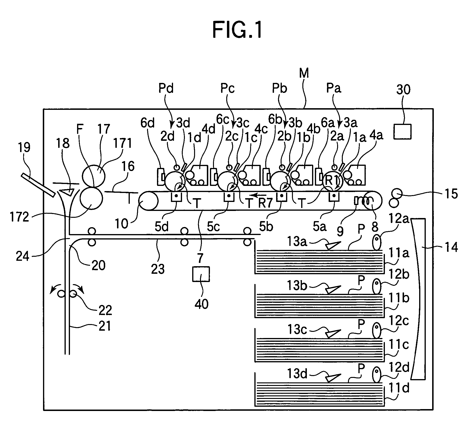
[0020]FIG. 1 shows an image forming apparatus to which the present invention can be applied. The image forming apparatus shown in FIG. 1 is a four-color full-color electrophotographic type image forming apparatus, and FIG. 1 is a view typically showing a longitudinal cross section in a direction along the conveying direction of a recording material P.

[0021]In the image forming apparatus shown in FIG. 1, first, second, third and fourth image forming portions (image forming means) Pa, Pb, Pc and Pd are provided inside an image forming apparatus main body M in succession from an upstream side along the direction of movement of the recording material P.

[0022]The image forming portions Pa, Pb, Pc and Pd are similar in construction to one another. The respective image forming portions Pa, Pb, Pc and Pd have drum-shaped electrophotographic photosensitive members (hereinafter referred to as the “photosensitive drum”) 1a, 1b, 1c and 1d, respectively, as image bearing members rotatable in the...

embodiment 2

[0046]In this embodiment, design is made such that the above-described backing sheet producing operation is performed during the standby of the image forming apparatus. The schematic construction of the image forming apparatus according to this embodiment is similar to that of the image forming apparatus according to the above-described Embodiment 1 described with reference to FIG. 1.

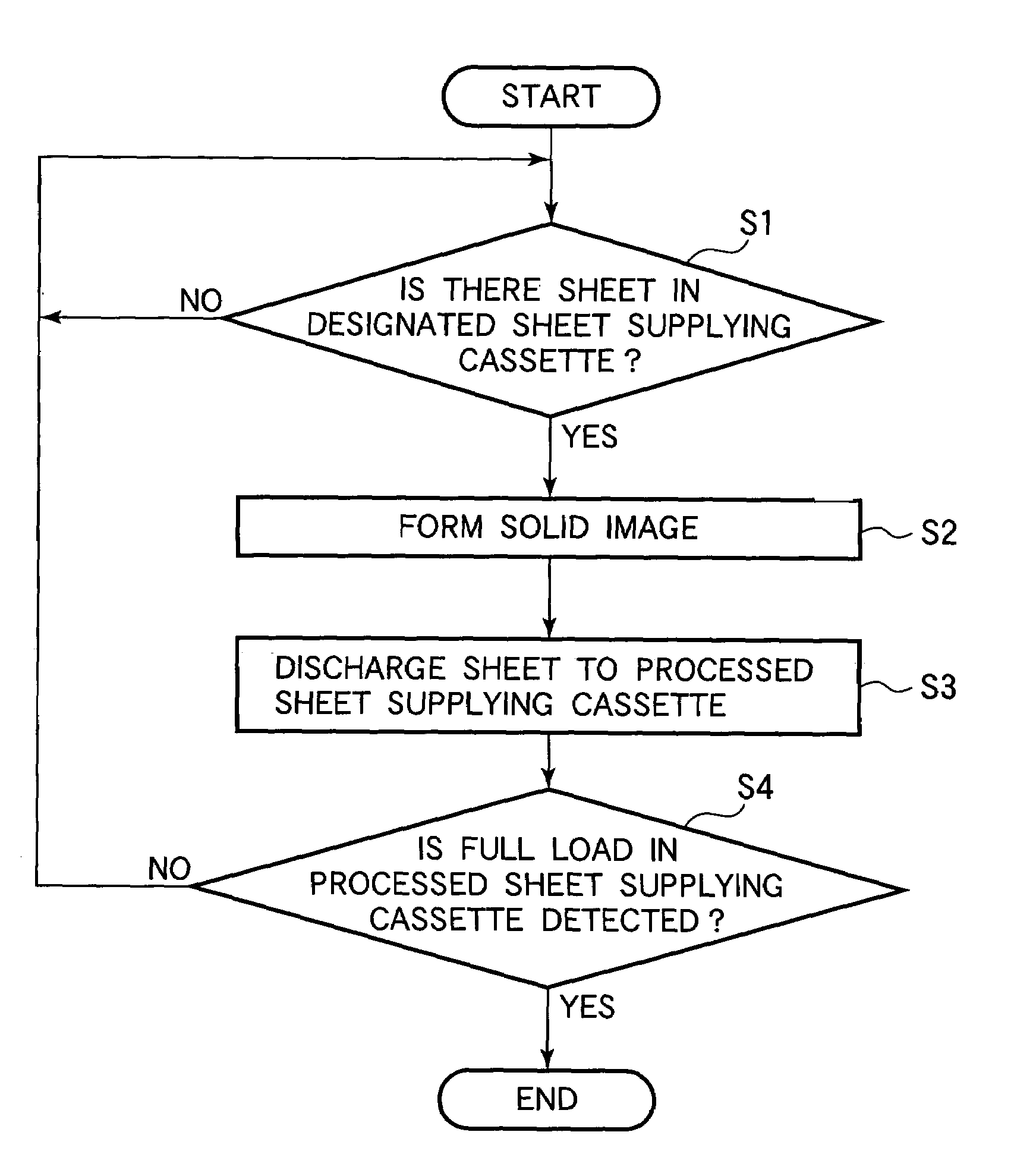
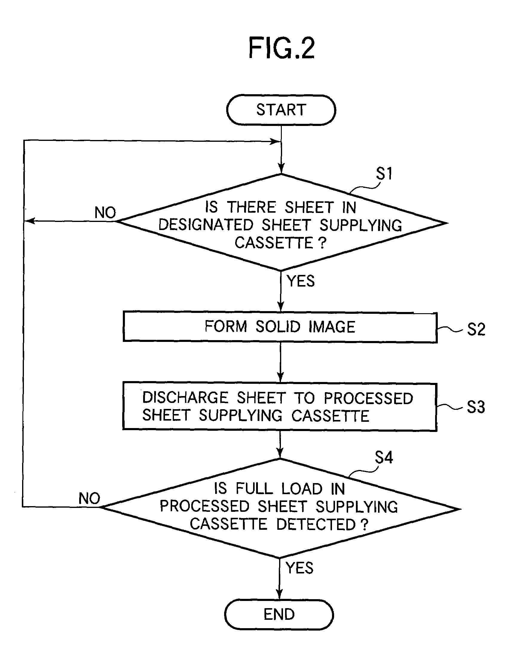
[0047]The backing sheet producing operation in the present embodiment will now be described with reference to FIG. 3.

[0048]First, it is to be understood that by the user, the backing sheet is set in one of the sheet supplying cassettes 11b, 11c and 11d with its back side facing downwardly. When the backing sheet producing key 301 is selected on the operating panel 30 and setting is effected to the selection of the sheet supplying cassette 11b, 11c or 11d in which the backing sheet on which the solid image processing is to be executed and to an automatic producing mode, the cassette presence or absence d...

embodiment 3

[0056]In this embodiment, when the sheet supplying cassette 11a for containing therein backing sheets subjected to solid image processing has become fully loaded, these backing sheets are conveyed to another sheet supplying cassette which is not in its fully loaded state.

[0057]The schematic construction of the image forming apparatus according to the present embodiment is substantially similar to that of the image forming apparatus described in the Embodiment 1 of FIG. 1. In the image forming apparatus according to the present embodiment, however, a conveying path similar to the conveying path 23 in FIG. 1 is disposed at a location corresponding to the sheet supplying cassettes 11b, 11c and 11d. That is, design is made such that a reversed backing sheet can be discharged to any one of the sheet supplying cassettes 11a, 11b, 11c and 11d.

[0058]The backing sheet producing operation in the present embodiment will now be described with reference to FIG. 4.

[0059]First, it is to be unders...


PUM


Abstract

An image forming apparatus having a visible image forming device for forming a visible image on a recording material in a visible image forming area, a supplying device provided with a containing portion for containing the recording material therein, and for supplying the recording material from the containing portion to the visible image forming area, a conveying device for conveying the recording material from the visible image forming area to the containing portion, and an executing device for executing a mode in which the supplying device supplies the recording material having the visible image formed thereon to the visible image forming area, the visible image forming device forms a visible image so as to superimpose it on the visible image formed on the recording material, and the conveying device conveys the recording material having the visible images formed thereon in superimposing relationship with each other to the containing portion.

Description

BACKGROUND OF THE INVENTION[0001]1. Field of the Invention[0002]The invention relates to an image forming apparatus, and particularly to an image forming apparatus which uses a recording material on one side of which an image has been formed.[0003]2. Related Background Art[0004]In recent years, the senses to environmental problems have been growing on the part of the users of image forming apparatuses. So, from the viewpoint of the saving of natural resources, reusable recording materials having an image formed on one side thereof, but having any image not yet formed on the other side thereof are extensively used. The reusable recording material having an image formed on one side thereof, but having an image not yet formed on the other side thereof will hereinafter be referred to as the backing sheet.[0005]Here, when the image formed on one side includes confidential information, the confidential information may leak out. As a method of preventing the leakage of such confidential in...

Claims


Application Information

Patent Timeline
Patent Type & Authority Patents(United States)
IPC IPC(8): G03G15/00
CPCG03G15/6508G03G2215/00299G03G2215/00894G03G2215/00932
Inventor NAKAMOTO, IKUO
Owner CANON KK
Learn More