Measurement Device

a measurement device and measurement technology, applied in the field of measurement devices, can solve the problems that the radiation pattern cannot be previously specified, and achieve the effect of reducing undesired radiation pattern deformation, facilitating recognition, and inhibiting the reduction of surface shape recognition accuracy

Inactive Publication Date: 2016-03-31
OPTON CO LTD
View PDF8 Cites 1 Cited by
  • Summary
  • Abstract
  • Description
  • Claims
  • Application Information

AI Technical Summary

Benefits of technology

[0015]Consequently, according to the one aspect of the measurement apparatus of the present invention, it is possible to easily recognize, as a surface shape in one space, the surface shapes in the respective radiation regions that have been recognized from a plurality of images.
[0016]Also, in the one aspect of the measurement apparatus of the present invention, the specific wavelengths of the specific wavelength lights radiated by the respective radiation devices have non-overlapping bandwidths. Therefore, according to the one aspect of the measurement apparatus of the present invention, if the specific wavelength lights (radiation patterns) from mutually different radiation devices overlap each other, occurrence of interference of light in an overlapping area can be reduced.
[0017]Thus, according to the one aspect of the measurement apparatus of the present invention, it is possible to reduce undesired deformation of the radiation patterns and to inhibit reduction in recognition accuracy of the surface shape of the measurement target.
[0018]As described above, according to the one aspect of the meas

Problems solved by technology

Accordingly, if dust attaches the outer surfaces of the optical elements provided to the housing, a previously specifi

Method used


Image

  • Measurement Device
  • Measurement Device
  • Measurement Device

Examples


Embodiment Construction

[0040]Hereinafter, an embodiment as an example of the present invention will be described with reference to the drawings.

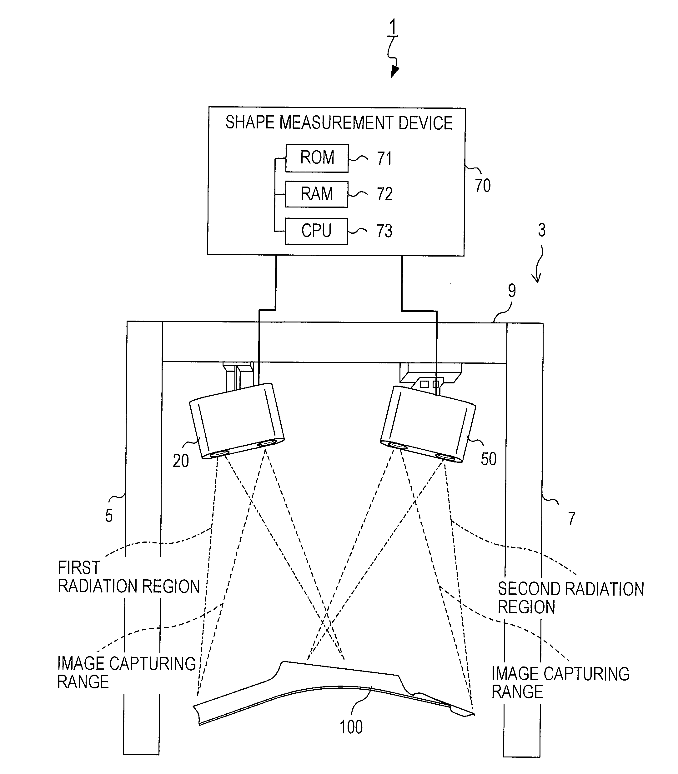
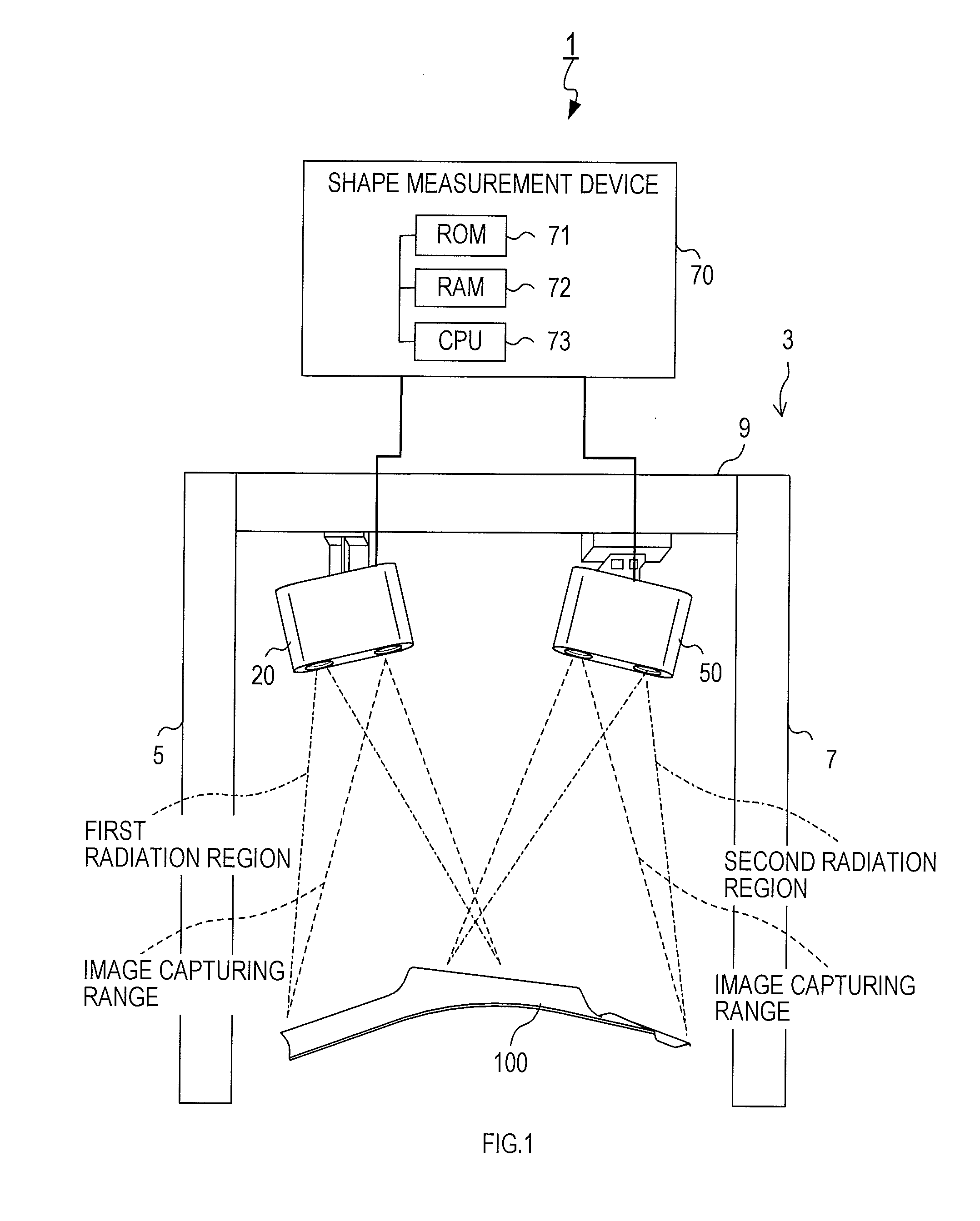
[0041]A measurement apparatus 1 shown in FIG. 1 is a system to measure a surface shape of a measurement target 100.

[0042]The measurement apparatus 1 comprises a frame 3, a first image capturing unit 20, a second image capturing unit 50, and a shape measurement device 70.

[0043]The frame 3 comprises side wall portions 5 and 7, and a top plate portion 9 extended between respective upper end portions of the side wall portions 5 and 7. In the present embodiment, the measurement target 100 is placed in an open space surrounded by the side wall portions 5 and 7, and the top plate portion 9.

[0044]The measurement target 100 is an object having an uneven surface. The measurement target 100 may be, for example, an industrial product that is mass produced in a factory.

[0045]Also, the measurement apparatus 1 may be used, in a situation where a large number of measurement targe...


PUM


Abstract

A measurement apparatus includes at least two or more radiation devices, at least two or more image capturing devices, and a measurement device. Each of the radiation devices radiates light such that a part of a radiation pattern overlaps a part of a radiation pattern from another one of the radiation devices on a measurement target. Each of the image capturing devices captures an image of a radiation region of the measurement target on which the radiation pattern of a specific wavelength light radiated by one of the radiation devices that is paired with the image capturing device is projected, through a specific wavelength pass filter that allows passage of light of a specific wavelength of the paired radiation device and blocks light of a wavelength except the specific wavelength.

Description

CROSS-REFERENCE TO RELATED APPLICATIONS[0001]This application is a 371 National Stage Application of International Application No. PCT / JP2014 / 080077, filed Nov. 13, 2014, published as WO 2015 / 093194 on Jun. 25, 2015, not in English, which is based on and claims the benefit of Japanese Patent Application No. 2013-259122 filed Dec. 16, 2013 in the Japan Patent Office, and the contents of which are hereby incorporated by reference in their entireties.FIELD OF THE DISCLOSURE[0002]The present invention relates to a measurement apparatus to measure a surface shape of a measurement target.BACKGROUND OF THE DISCLOSURE[0003]Measurement apparatuses for measuring a surface shape of a measurement target by three-dimensional measurement have been known. A known measurement apparatus of this type includes an image capturing unit and a shape recognition device.[0004]The image capturing unit is a unit that radiates light having a specified radiation pattern, and captures an image of a region to whi...

Claims


Application Information

Patent Timeline
IPC IPC(8): G01B11/25H04N5/225H04N5/247
CPCG01B11/25H04N5/247H04N5/2256H04N5/2252G01B11/245G06T2207/10012G06T2207/10024G06T2207/10152G06T2207/30164G03B17/55G03B35/08G06T7/521H04N23/56H04N23/51H04N23/90
Inventor YOGO, TERUAKITANAKA, HIDEYUKI
Owner OPTON CO LTD
Why Eureka
Try Eureka