Transmit-array antenna comprising a mechanism for reorienting the direction of the beam

a beam direction and beam technology, applied in the field of transmitarray antennas, can solve the problems of higher production cost, complex and more expensive high frequency implementation, and lower dynamic performance levels, and achieve the effects of increasing complexity, increasing production costs, and increasing complexity

Active Publication Date: 2019-01-03
RADIALL SA
View PDF0 Cites 1 Cited by
  • Summary
  • Abstract
  • Description
  • Claims
  • Application Information

AI Technical Summary

Benefits of technology

[0080]Another solution that may be contemplated by a person skilled in the art involves multiplying the number of sources (or of receivers) in the focal plane and successively supplying them with electrical power through selective switching (publication [2]). The relative movement between the focal sources and the transmit-array would then be unnecessary, but this would involve, on the one hand, greater complexity and thus higher production costs and, on the other hand, angular discretization of the depointing of the beam.
[0081]Indeed, the more directive the antenna, the narrower its main beam. Thus, in order to cover the same given angular sector (for example, + / −10 degrees) with a more directive antenna (for example, 40 dBi instead of 30 dBi), the number of focal sources would need to be multiplied, thus increasing the complexity and the production cost.

Problems solved by technology

This type of antenna is commonly implemented for radar applications but not for fixed point-to-point connection applications, which require lower dynamic performance levels and which have a lower acceptable manufacturing cost.
They have the disadvantages of being more complex and more expensive to implement at high frequencies, such as at the millimeter wave frequencies, in particular in the 28-140 GHz range, and at the dimensions required to obtain high gains, typically greater than 25 decibels relative to isotropic (dBi).
Finally, intrinsically, phased-array antennae are less efficient than transmit-array antennae due to the greater electrical losses introduced by the supply network and the phase shifting circuits.
Furthermore, their energy consumption is generally higher.
The disadvantages of this solution are a scanning speed that is limited by the dynamic performance levels of the gimbal system, a lifetime that is limited by the wear of the movable parts and greater sensitivity to vibrations.
However, none of the solutions has yet been able to be implemented in the V (57-66 GHz) or E (71-86 GHz) bands.
Indeed, when the frequency increases, the size of the basic cell of the transmit-array, proportional to the wavelength, decreases and no technology exists for producing the phase shifting circuits within the dimension constraint required in these bands and at an acceptable cost for fixed point-to-point connection telecommunication applications.
No dynamic depointing solution allowing the direction of the beam to be dynamically controlled has been contemplated to date for transmit-array antennae.

Method used


Image

  • Transmit-array antenna comprising a mechanism for reorienting the direction of the beam
  • Transmit-array antenna comprising a mechanism for reorienting the direction of the beam
  • Transmit-array antenna comprising a mechanism for reorienting the direction of the beam

Examples


Embodiment Construction

[0084]Further advantages and features of the invention will become more clearly apparent upon reading the detailed description of embodiments of the invention, which is provided by way of a non-limiting example, with reference to the following figures, in which:

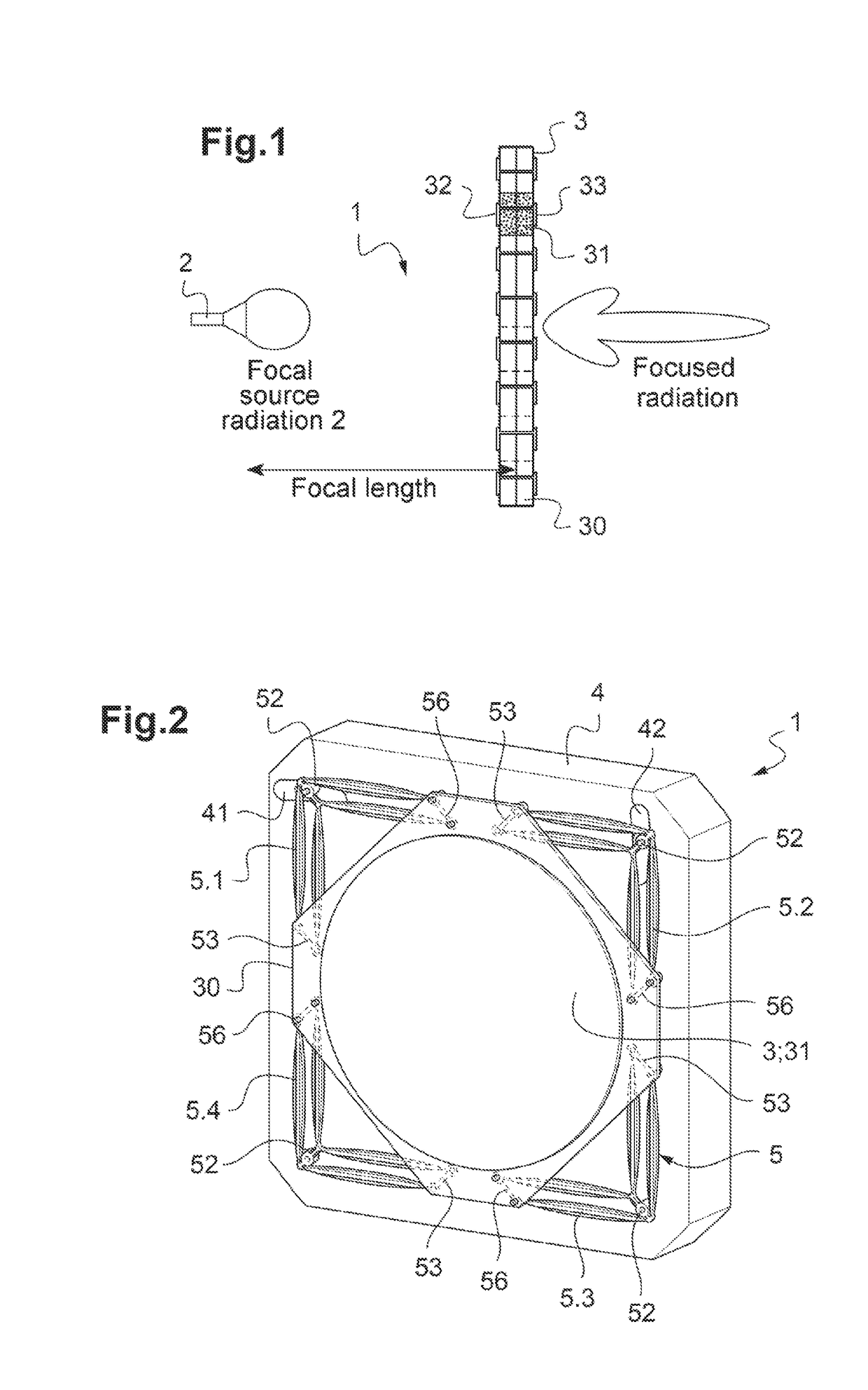
[0085]FIG. 1 is a schematic view of a reflector-array antenna according to the prior art;

[0086]FIG. 2 is a perspective view of a reflector-array antenna according to the invention provided with its four-pantograph mechanism for moving the transmit-array;

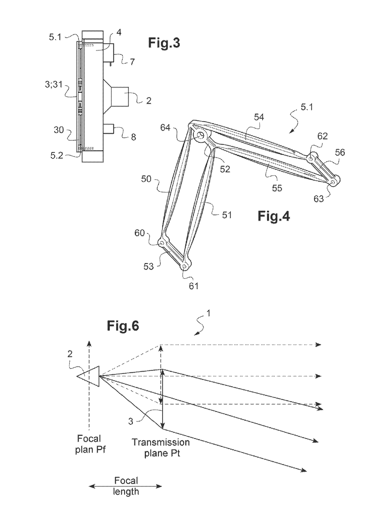
[0087]FIG. 3 is a side view of the antenna according to FIG. 2;

[0088]FIG. 4 is a perspective view of one of the pantograph devices of the mechanism for moving the reflector-array according to the invention;

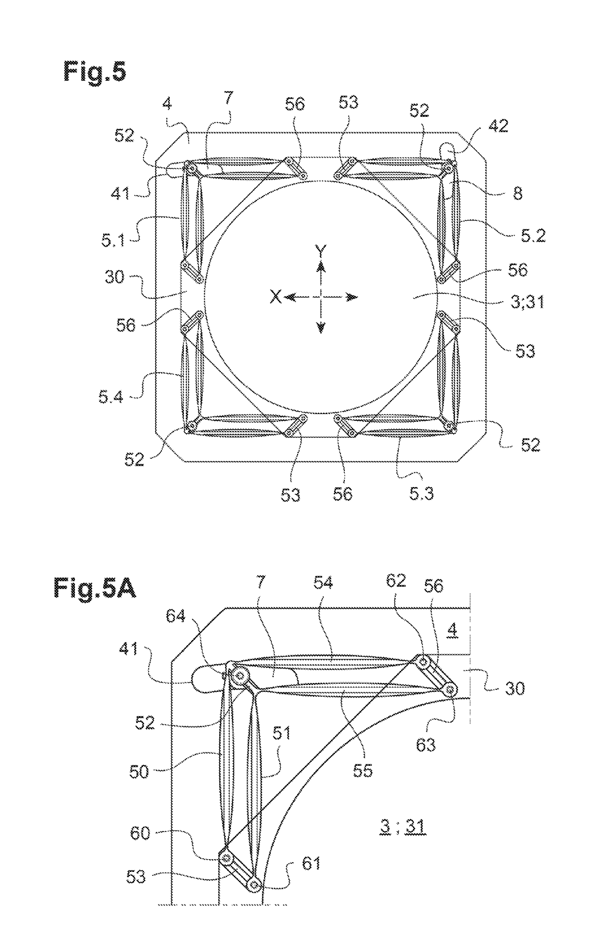
[0089]FIG. 5 is a front view of the antenna according to FIG. 2;

[0090]FIG. 5A is a detailed view of FIG. 5 showing the connection of one of the pantograph devices to one of the servomotors for translationally moving the transmit-array in a direction;

[0091]FIG. 6 is a schemat...


PUM


Abstract

The present invention relates to a transmit-array radiofrequency antenna comprising: a support; a transmit-array arranged in a plane, called a transmission plane; at least one focal source fixed on the support and arranged at the focal length from the array; and a displacement mechanism for moving the transmit-array, the mechanism being connected to the support and being adapted to translationally move the transmit-array in at least one of the two directions in the transmission plane.

Description

TECHNICAL FIELD[0001]The present invention relates to the field of transmit-array antennae.[0002]More specifically, it contemplates proposing a solution for dynamically reorienting the direction of the antenna beam.[0003]The preferred applications contemplated by the invention are antennae operating in the microwave range, preferably in the range between 57 to 66 GHz. However, the invention is also applicable over the entire millimeter wave frequency band (30 to 300 GHz). The market that is mainly contemplated by the invention is that of fixed point-to-point connections, with a distance typically ranging between 100 m and 10 km, at high bit rates, typically from 1 to 10 Gbits, for telecommunication applications. This type of connection is mainly used in infrastructures for mobile networks for the 4G, 5G standards, in the dedicated connections between buildings (campus, companies) and is considered to be key technology for the future 5G access points intended to be integrated in urba...

Claims


Application Information

Patent Timeline
Patent Type & Authority Applications(United States)
IPC IPC(8): H01Q19/06H01Q19/08H01Q3/14G01S13/42
CPCH01Q19/062H01Q19/08H01Q3/14G01S13/426H01Q15/06H01Q21/0018
Inventor HUCHARD, MATHIEUBARBIER, CYRILPETIT, LAURENT
Owner RADIALL SA
Why Eureka
Try Eureka