
Button-attaching device and method of attaching button to upper die of button-attaching device

a button and upper die technology, applied in the field of button-attaching devices and methods of button-attaching devices, can solve the problems of affecting the workability of workers, affecting the circumferential position of the design, and affecting the operation of the button-attaching device, so as to facilitate the circumferential positioning of the button

Active Publication Date: 2009-02-17
YKK CORP
View PDF21 Cites 2 Cited by
  • Summary
  • Abstract
  • Description
  • Claims
  • Application Information

AI Technical Summary

Benefits of technology

[0007]An object of the present invention is to provide a button-attaching device and a method of fixing a button to an upper die of the button-attaching device which can enable an operator to fix the button to the upper die with an easy circumferential positioning of the button and without holding an attachment part of the button.
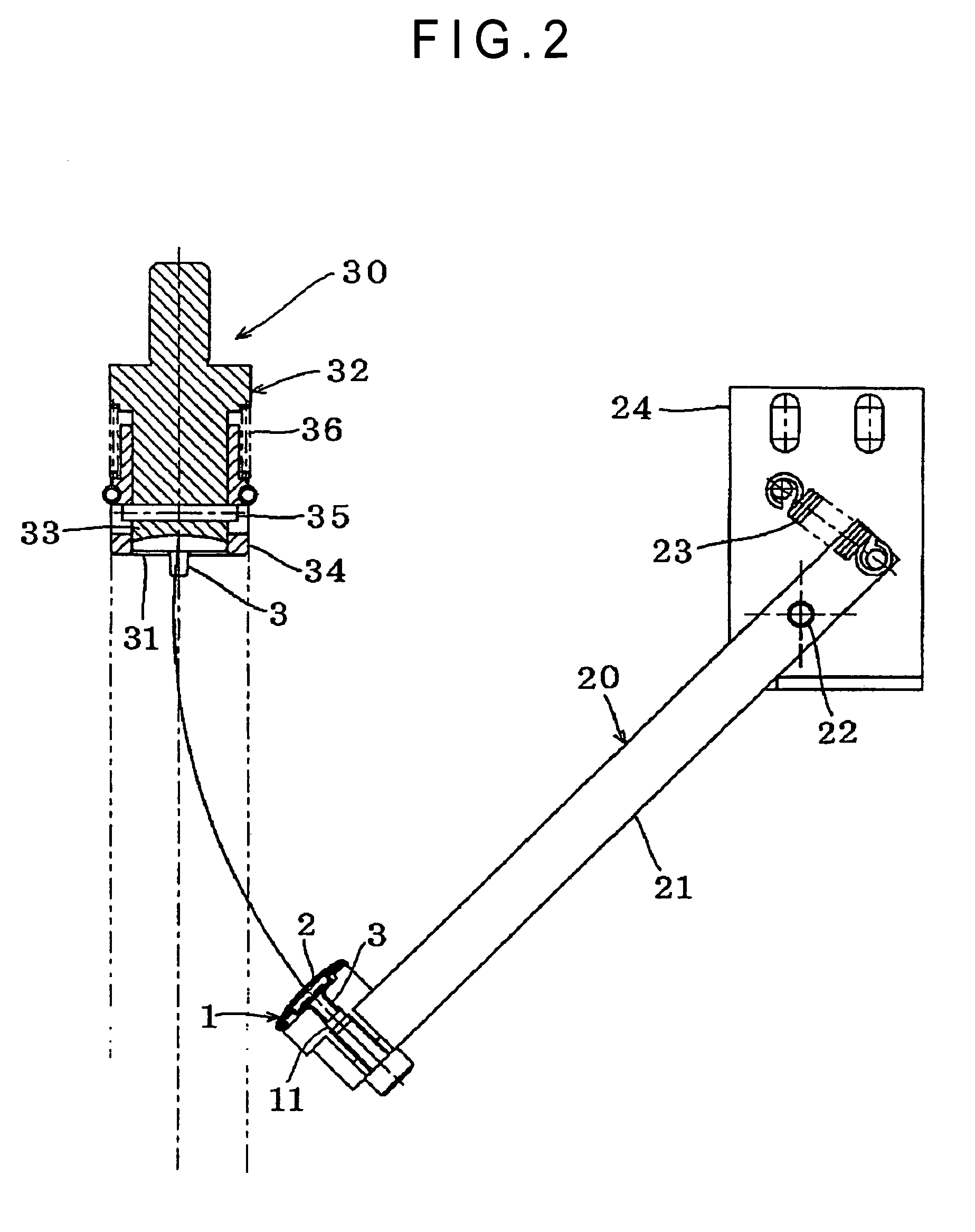
[0014]By rotating the button holder along a circular trajectory between the button holding position and the button transferring position, it becomes unnecessary to move the button holder in a direction other than the circular trajectory. More specifically, in a case where, for instance, the button holder is moved vertically, when the upper die is lifted down, the button holder must be moved in a direction other than the vertical direction (i.e., horizontal direction) in order to move the button holder outside the lifting path of the upper die. Even in a case where the button holder is moved horizontally, at least a slight vertical movement of the button holder is required in transferring the button from the button holder to the upper die. However, according to the aspect of the present invention, by moving the button holder along the circular trajectory, the button holder can be properly moved outside the lifting path when the upper die is lifted down.
[0020]With the arrangement of the present invention, even when the button does not have the notch or the tab, the button can be set on the button holder by observing the design of the upper face of the button as described above. Therefore, the circumferential positioning of the button can be facilitated as compared to the case where the upper face of the button cannot be observed. Incidentally, when the button has the notch or the tab, and further, the button holder is provided with the corresponding projection or dent, the setting operation of the button can be performed even more easily and precisely.

Problems solved by technology

Note that, there is another method in which the button is fixed to the lower die, but the method causes the button to be placed under the garment fabric and impedes the operator from observing the attaching position on the garment fabric.
Thus, when the upper face of the button has a design that is orientated, the operator cannot observe the upper face of the button in fixing the button to the upper die, which might cause a circumferential position of the design to be displaced.
In addition, much attention is required to perform such positioning work precisely, resulting in degrading workability.
Further, since the button is inserted and fixed to a dented fixing part of the upper die, the operator has to hold with his / her fingers the above-described attachment part (eyelet, prong, etc.) that shapes like a pin projecting from a body of the button, so that the operator feels pain on the fingers after a long work.

Method used


Image

  • Button-attaching device and method of attaching button to upper die of button-attaching device
  • Button-attaching device and method of attaching button to upper die of button-attaching device
  • Button-attaching device and method of attaching button to upper die of button-attaching device

Examples


Embodiment Construction

[0030]Although a preferred embodiment of the present invention will be described referring to the attached drawings, the present invention is not limited thereto.

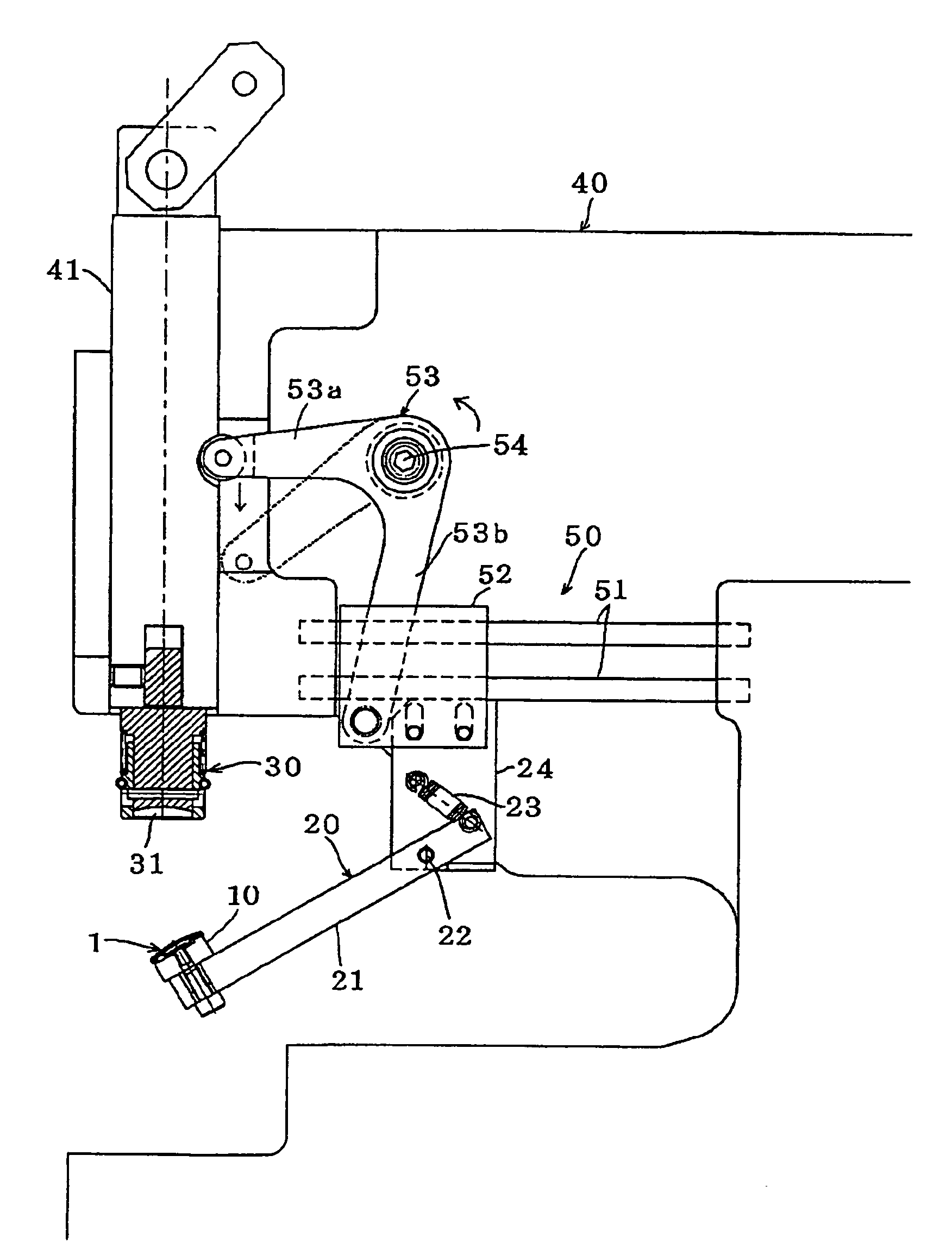
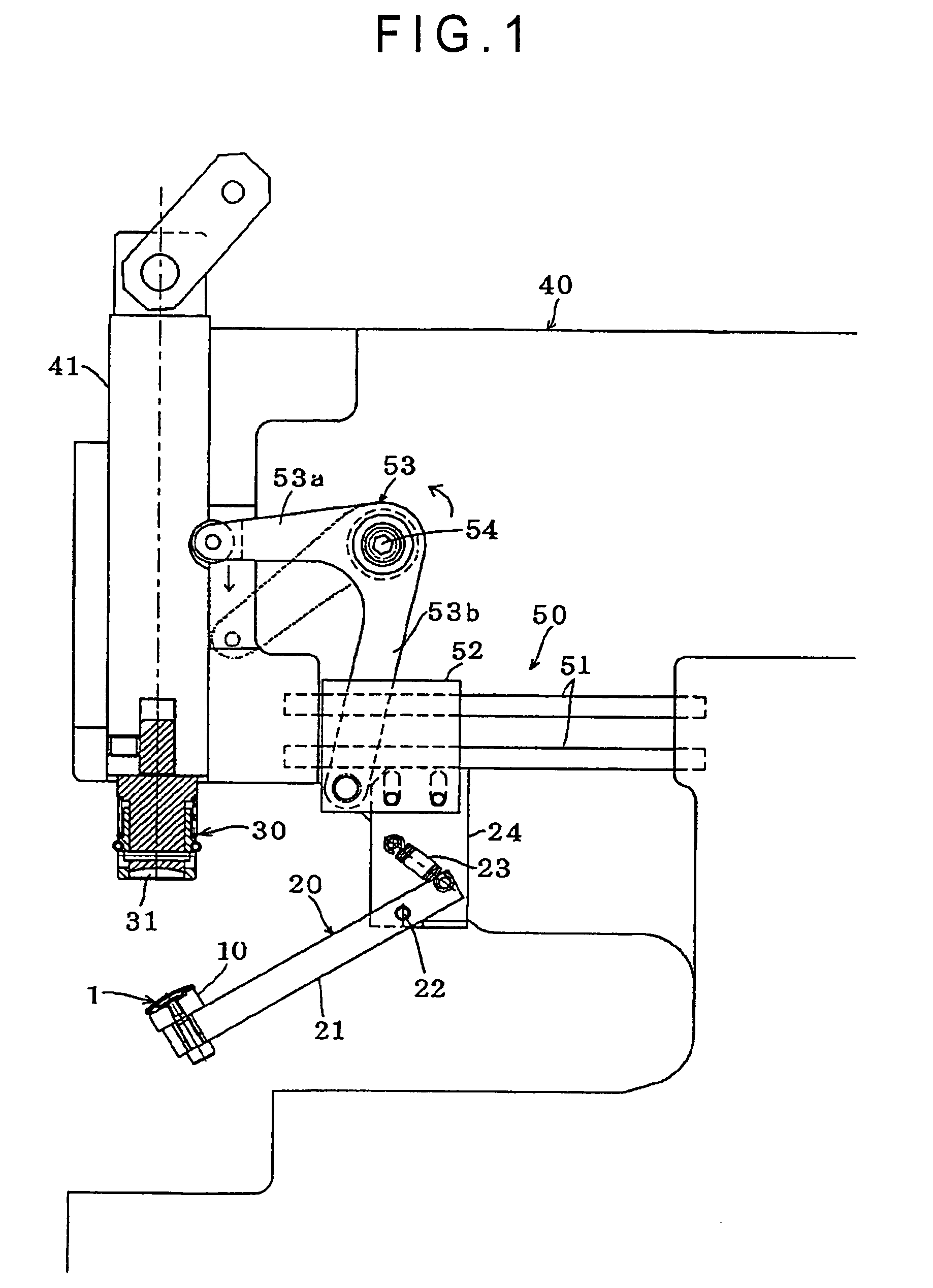
[0031]FIG. 1 is a partial side view schematically showing a button-attaching device 40 according to the present invention, which shows an example of how a later-described snap upper chuck unit (a combination of a button holder and a button holder moving unit) is provided to a button-attaching device body.

[0032]The button-attaching device includes an upper die 30 shown in its standby position (uppermost position) and a lower die (not shown) disposed on the lower side of the upper die 30, the upper die 30 lifted up and down by a plunger 41. The button-attaching device 40 is provided with the snap upper chuck unit (hereinafter simply referred to as “chuck unit”) 20, the chuck unit 20 including the button holder 10 for holding a button 1 and the button holder moving unit for circularly moving the button holder 10, the button ho...


PUM

PropertyMeasurementUnit
workabilityaaaaaaaaaa
circumferenceaaaaaaaaaa
areaaaaaaaaaaa

Abstract

A button-attaching device 40 includes a snap upper chuck unit 20. A button holder 10 of the chuck unit 20 temporarily holds a button 1, and the button holder 10 is then rotated by a rotating arm 21, so that the button 1 is transferred from the button holder 10 to a button fixing part 31 of an upper die 30.

Description

TECHNICAL FIELD[0001]The present invention relates to a button-attaching device and a method of fixing a button to an upper die of the button-attaching device, more specifically to an improved button-attaching device in which a button is fixed to an upper die and a new method of fixing the button to the upper die which is implemented in the improved device.BACKGROUND ART[0002]Conventionally, there have been generally used button-attaching devices in attaching a button to a fabric of a garment or the like in the industry (see, for instance, Japanese Patent Applications No. 58-9799 and No. 4-163304 and Japanese Utility Model Application No. 60-189524).[0003]The button-attaching devices described above each include an upper die that can be lifted up and down and a lower die that is supported on the lower side of the upper die. When a button is attached using these button-attaching devices, first, the button is fixed to the upper die, and then a socket or a stud as a coupler coupling wi...

Claims


Application Information

Patent Timeline
Patent Type & Authority Patents(United States)
IPC IPC(8): A41H37/10
CPCA41H37/10Y10T29/49826
Inventor HACHISU, YOSHINORI
Owner YKK CORP
Learn More