Gas-powered glue gun

a gas-powered glue gun and gas-powered technology, which is applied in the field of gas-powered glue guns, can solve the problems of high operative cost, difficult to leave the combustion chamber with hot exhaust, and high cost of use, and achieve the effect of low cost in us

Active Publication Date: 2008-05-06
LIN ARLO
View PDF16 Cites 6 Cited by
  • Summary
  • Abstract
  • Description
  • Claims
  • Application Information

AI Technical Summary

Benefits of technology

[0009]The primary advantage of the glue gun according to the present invention is a low cost in use since the heat is well reserved.

Problems solved by technology

Problems have been encountered in the use of the glue gun 80.
This entails a high operative cost.
Secondly, it is difficult for hot exhaust to leave the combustion chamber 10 through the exhaust port 21 because the hot exhaust tends to rise while the exhaust port 21 extends downwards.
An undesired amount of heat accumulates in the combustion chamber 10.
This high temperature may damage the glue gun and hurt a user.
Therefore, it is hard to expel hot exhaust.

Method used


Image

  • Gas-powered glue gun
  • Gas-powered glue gun
  • Gas-powered glue gun

Examples


Embodiment Construction

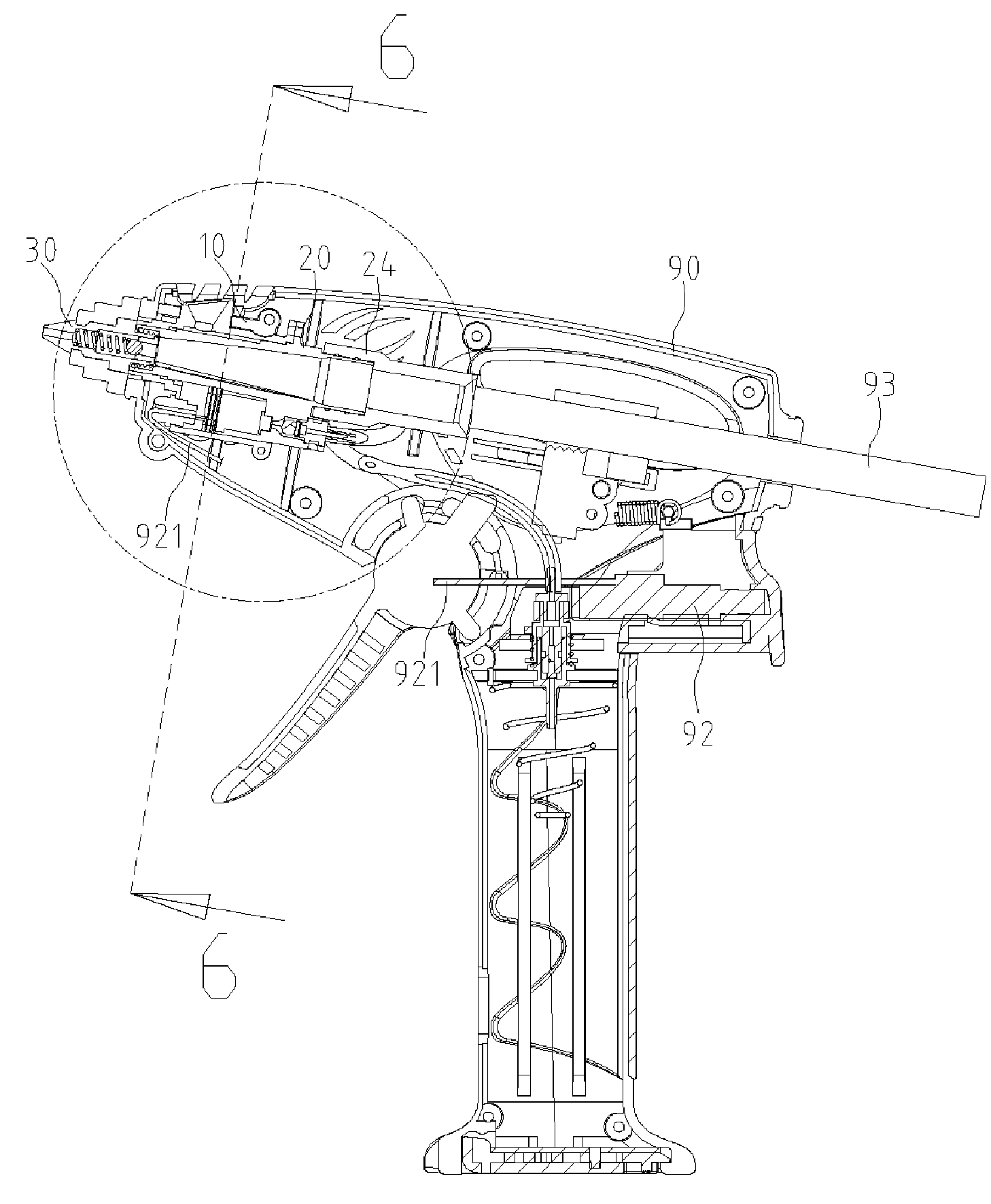
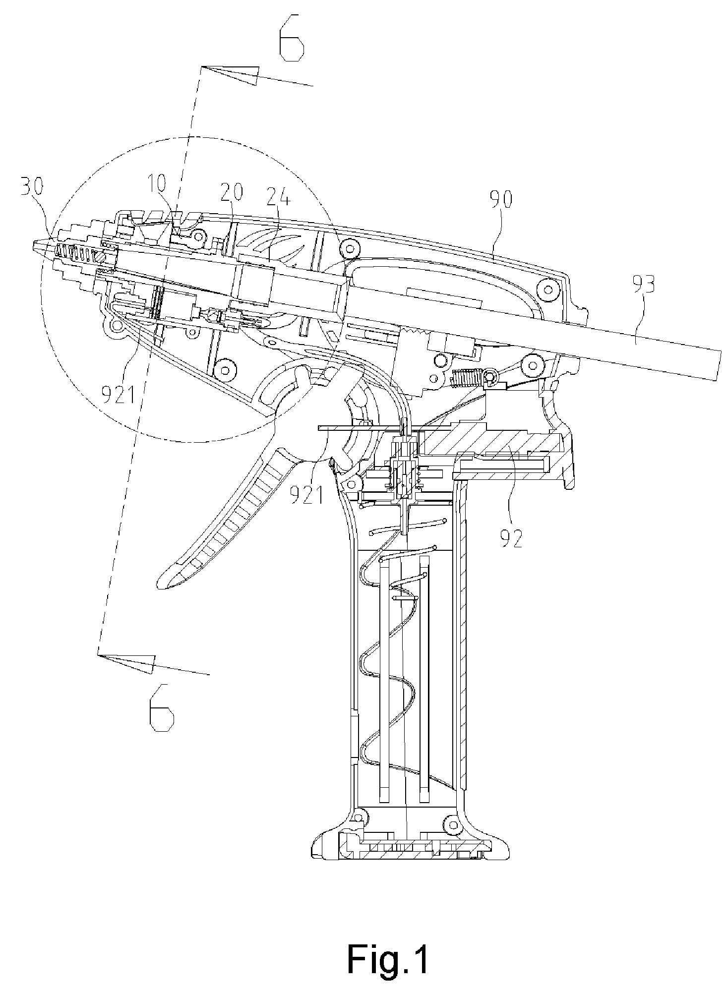
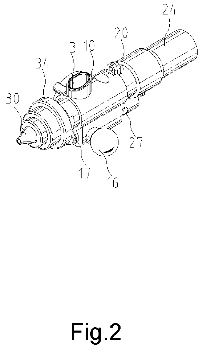
[0018]Referring to FIGS. 1 through 6, a gas-powered glue gun includes a shell 90, a burner 10, a mixture chamber 26, a barrel 20 and a dispenser 30 according to the preferred embodiment of the present invention.

[0019]The burner 10 includes a combustion chamber 12, a thermal chamber 11 formed next to the combustion chamber 12, an exhaust port 13 formed on the thermal chamber 11, a seat 14 formed on a side of the combustion chamber 12 and the thermal chamber 11, a window 15 defined in the combustion chamber 12 and a magnifier 16 for covering the window 15. The magnifier 16 is preferably a glass ball. A piezoelectric ceramic ring 17 is fit in an aperture defined in a front portion of the combustion chamber 12. An ignition lead 921 of a piezoelectric switch 92 is inserted into the combustion chamber 12 through the piezoelectric ceramic ring 17. A catalytic net 18 is disposed in the combustion chamber 12 to prevent fierce flames. A security device 91 is disposed in the seat 14.

[0020]Inhe...


PUM


Abstract

A glue gun includes a shell, a burner, a mixture chamber, a barrel and a dispenser. The burner is disposed in the shell and formed with a combustion chamber and a thermal chamber. The mixture chamber is connected to the combustion chamber. The barrel is inserted through the thermal chamber. The dispenser is connected to the barrel. Gas is mixed with air in the mixture chamber. The mixture is sent into the combustion chamber from the mixture chamber. Heat is generated as the mixture is ignited and combusted in the combustion chamber. The thermal chamber transfers the heat to the barrel from the combustion chamber. The barrel heats and melts a glue stick inserted therein. The dispenser dispenses the molten glue from the barrel.

Description

CROSS-REFERENCE[0001]The present application is a continuation-in-part of U.S. Patent application Ser. No. 11 / 028,019 filed on Jan. 3, 2005, now abandoned.BACKGROUND OF INVENTION[0002]1. Field of Invention[0003]The present invention relates to an efficient gas-powered glue gun.[0004]2. Background of Invention[0005]According to U.S. Pat. No. 5,799,648, a conventional glue gun 80 includes a shell 81 including a main portion 82 and a handle portion 83. A main body 85 is installed in the main portion 82 of the shell 81. The main body 85 defines a combustion chamber 10 and an exhaust port 21 in communication with the combustion chamber 10. A combustion element 12 is disposed in the combustion chamber 10. A barrel 84 is disposed in the main portion 82 of the shell 81. The barrel 84 is connected with the main body 85 so that heat can be transferred to the barrel 84 from the main body 85. Solid glue is fed into the barrel 84. The solid glue is heated and molten in the barrel 84. The molten ...

Claims


Application Information

Patent Timeline
Patent Type & Authority Patents(United States)
IPC IPC(8): B65D5/66B44D3/16B67D7/80
CPCB05C17/00526B05C17/00546
Inventor LIN, ARLO
Owner LIN ARLO
Why Eureka
Try Eureka