Adapter for attaching an insertion device to a cable fitting

Inactive Publication Date: 2008-05-06
WEIDMULLER INTERFACE GMBH & CO KG
View PDF11 Cites 32 Cited by
  • Summary
  • Abstract
  • Description
  • Claims
  • Application Information

AI Technical Summary

Benefits of technology

[0012]The invention provides a standardized design, especially in the area of the portion that is to be sealed off between the cable sleeve of the cable passage and the sliding outer member; it does so with simple means and in a decisive fashion so that one can achieve a high degree of tolerance and mechanical and chemical resistance. The adapter furthermore can be used for plug parts of the most varied kind without basically having to alter the design to attain a high protective class such as IP65 or IP67.
[0014]According to another advantageous feature of the invention, at least one plug part is mounted in an auxiliary frame that can be inserted into the plug chamber at the rectangular end of the adapter body. Preferably, the auxiliary frame can also be locked in the receiving housing. The auxiliary frame makes it possible in the simplest way to insert various plug elements in uniformly shaped receiving housings. The need for having various receiving housings ready is thus obviated. It is also conceivable that some plug parts can be attached with the auxiliary frame and that differently shaped plug parts can be inserted directly without an auxiliary frame in the receiving housing and can be locked there.

Problems solved by technology

This known design, however, presents a problem in that it is suitable only for the transmission of electrical signals and that, as a rule, it is necessary to enlarge the structural space in order to use the solution also for other plug parts, for example, in light conductor techniques (for instance, SC simplex uses, especially at an interval of 7.35 mm).

Method used


Image

  • Adapter for attaching an insertion device to a cable fitting
  • Adapter for attaching an insertion device to a cable fitting
  • Adapter for attaching an insertion device to a cable fitting

Examples


Embodiment Construction

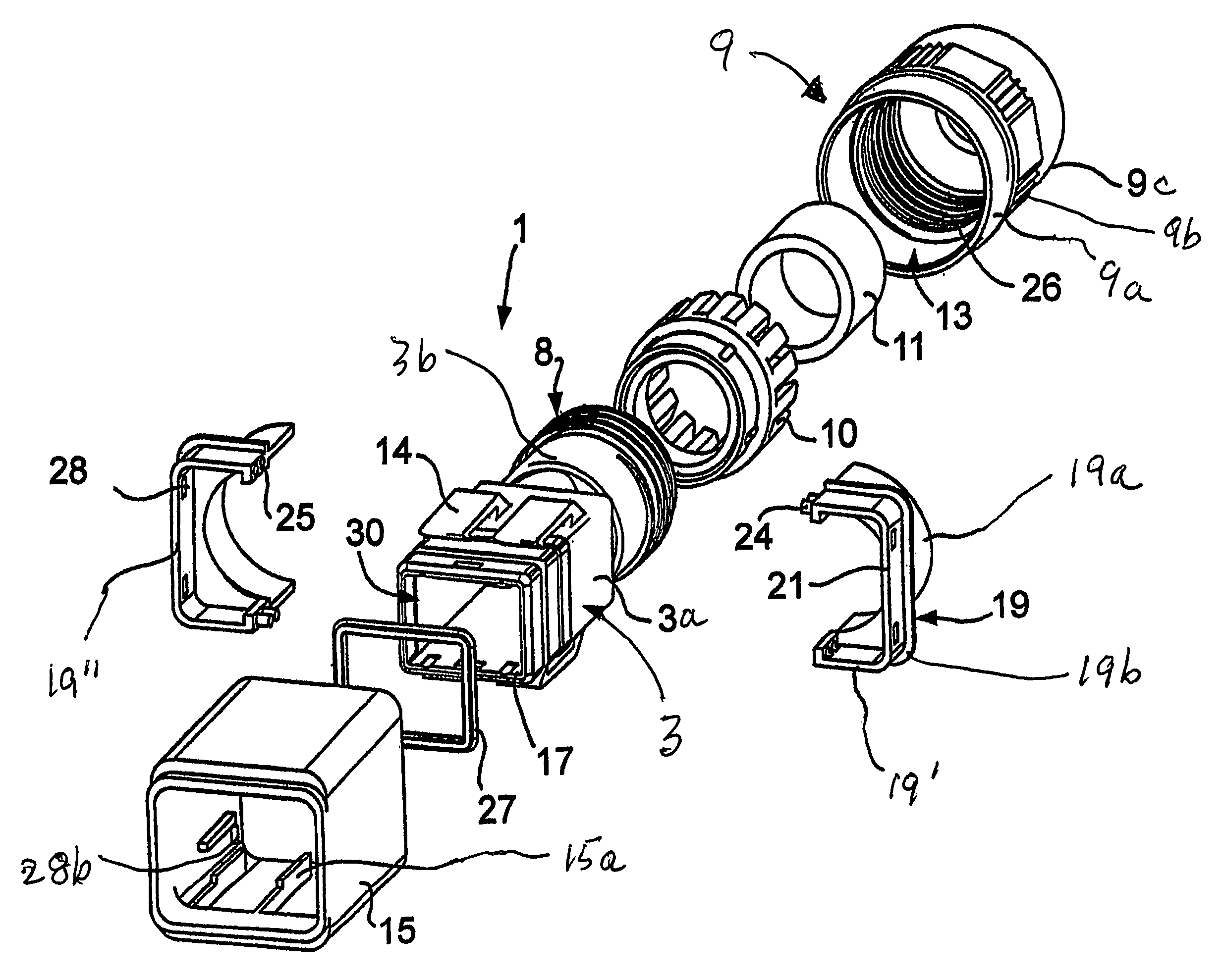
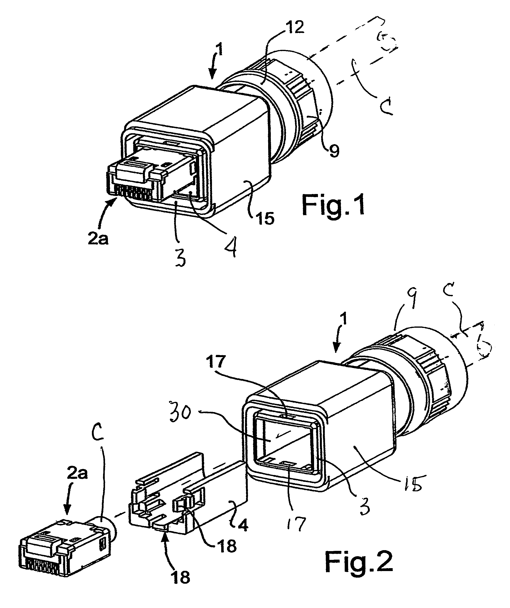
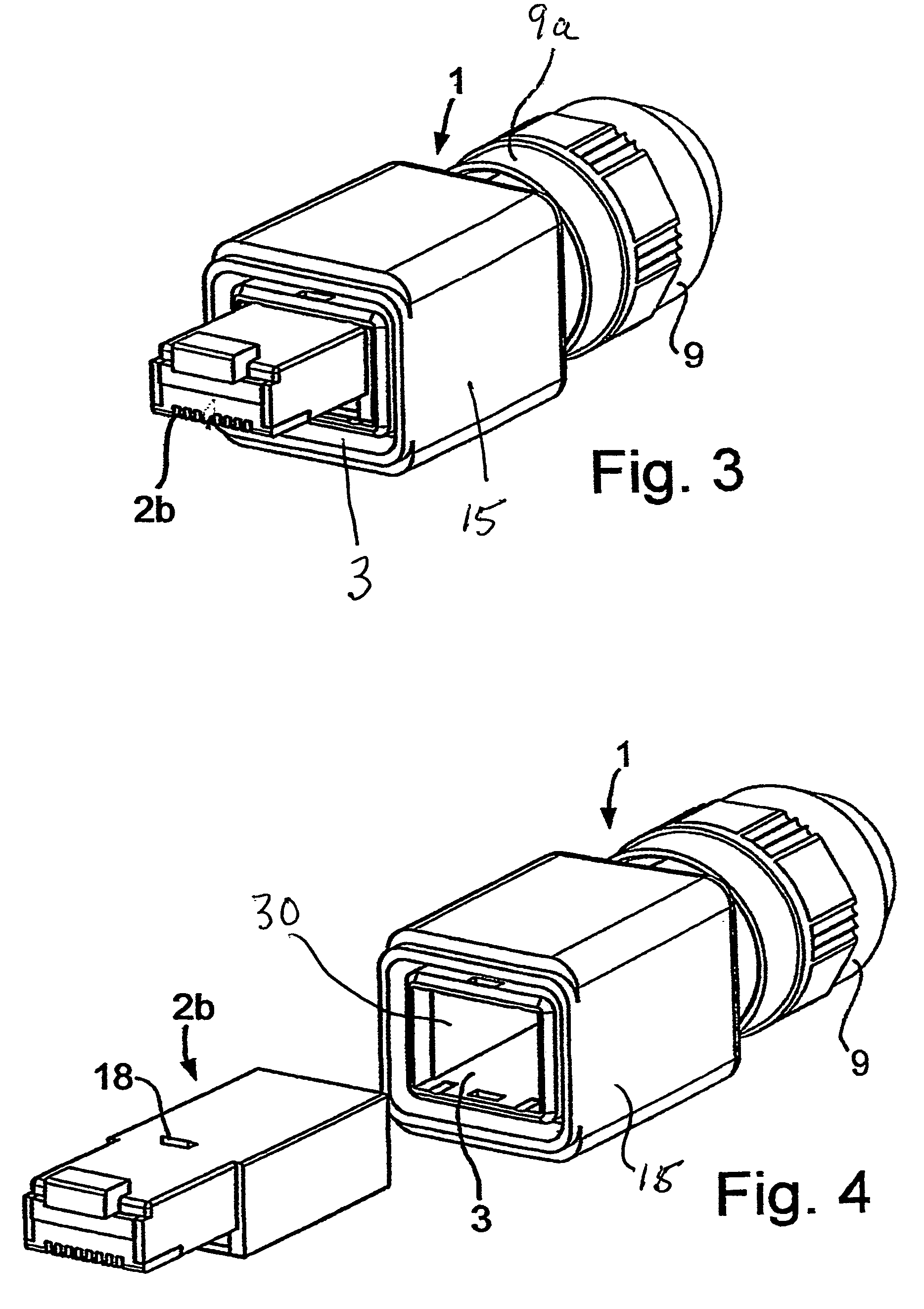
[0029]Referring first more particularly to FIGS. 1, 2, and 11, the adapter assembly 1 includes an adapter body 3 having a first rectangular end portion 3a, and a second tubular end portion 3b, as best shown in FIG. 11. The adapter body 3 contains a through passage which defines in the rectangular first end portion 3a a plug-receiving chamber 30 having a generally rectangular cross-sectional configuration, thereby to receive an electrical plug 2a, such as an RJ45 plug, that is connected with the cable C that extends through the adapter body. The cylindrical outer surface of the tubular second end portion 3b of the adapter body is provided with external screw threads 8. Arranged concentrically about the tubular second end portion 3a of the adapter body is a tubular cable sleeve 9 formed of a synthetic plastic material or metal having a tubular first end portion 9a, an internally threaded intermediate portion 9b provided with the screw threads 26, and a second tubular end portion 9c. A...


PUM


Abstract

An adapter assembly for connecting a multi-contact electrical plug within a cable support arrangement includes an elongated adapter body containing a through passage and having a rectangular first end portion containing a chamber for receiving the electrical plug, and a tubular second end portion threadably connected adjacent its free extremity with a concentrically arranged cable sleeve, an annular sealing device being provided for sealing one end of the annular space defined between the cylindrical outer surface of the adapter body tubular end portion and the inner surface of the adjacent end portion of the concentrically arranged sleeve. A second annular seal is supported within the cable sleeve for sealing the entrance of the cable into the adapter through passage, and a third sealing ring is provided for sealing the space between the outer surface of the adapter body rectangular end portion and a slidably mounted outer sleeve member.

Description

CROSS REFERENCE TO RELATED APPLICATIONS[0001]This application is a companion application to the U.S. application Ser. No. 11 / 641,433 filed Dec. 19, 2006, in the names of Claudia Hanning et al entitled “Adapter Housing for Connecting Insert Devices With a Cable Fitting”.BACKGROUND OF THE INVENTION[0002]1. Field of the Invention[0003]An adapter assembly is provided for connecting a multi-contact electrical plug within a cable support arrangement, including an elongated adapter body containing a cable-receiving through passage and having a rectangular first end portion containing a chamber for receiving an electrical plug connected with the cable, and a tubular second end portion threadably connected at its free end with a concentrically arranged cable sleeve, annular sealing means being provided for sealing one end of the annular space defined between the cylindrical outer surface of the adapter body tubular end portion and the inner surface of the adjacent end portion of the concentr...

Claims


Application Information

Patent Timeline
Patent Type & Authority Patents(United States)
IPC IPC(8): H01R13/213
CPCG02B6/3879G02B6/3887H01R13/6273H01R31/06H01R24/62G02B6/38875
Inventor MUHS, ANDREASHANNING, CLAUDIAZIEMKE, JUERGENHOEING, MICHAELSCHNATWINKEL, MICHAELMUECKE, MICHAELASEEREINER, SIMONLUETKEMEIER, ULRICH
Owner WEIDMULLER INTERFACE GMBH & CO KG
Why Eureka
Try Eureka