Device for fastening a fluid duct to a turbojet casing

a fluid duct and turbojet technology, which is applied in the direction of machines/engines, screw threaded joints, light and heating apparatus, etc., can solve the problems of inability to pass through the insides of the flame-holder arms, the space available between the outer casing of the after-burner chamber and the internal cylindrical wall downstream from the burner ring is too small for it to be possibl

Active Publication Date: 2008-05-13
SN DETUDE & DE CONSTR DE MOTEURS DAVIATION S N E C M A
View PDF4 Cites 18 Cited by
  • Summary
  • Abstract
  • Description
  • Claims
  • Application Information

AI Technical Summary

Benefits of technology

[0005]An object of the present invention is to provide a solution to this problem that is simple, effective, and inexpensive.

Problems solved by technology

It would be advantageous to house the fuel feed ducts of the burner ring inside outer end portions of the flame-holder arms in order to protect these ducts from the primary flow which is at a high temperature (that can reach about 2000°K in after-burner mode, for example) and in order to avoid disturbing the primary flow, but known means for fastening such ducts to the outer casing have parts that pass through the wall that are of relatively large diameter, so they are unsuitable for passing via the insides of the flame-holder arms.
In addition, the space available between the outer casing of the after-burner chamber and the internal cylindrical wall downstream from the burner ring is too small for it to be possible from the inside to fasten these feedthrough parts to the outer casing by using tools engaged inside the outer casing downstream from the burner ring.

Method used


Image

  • Device for fastening a fluid duct to a turbojet casing
  • Device for fastening a fluid duct to a turbojet casing
  • Device for fastening a fluid duct to a turbojet casing

Examples


Embodiment Construction

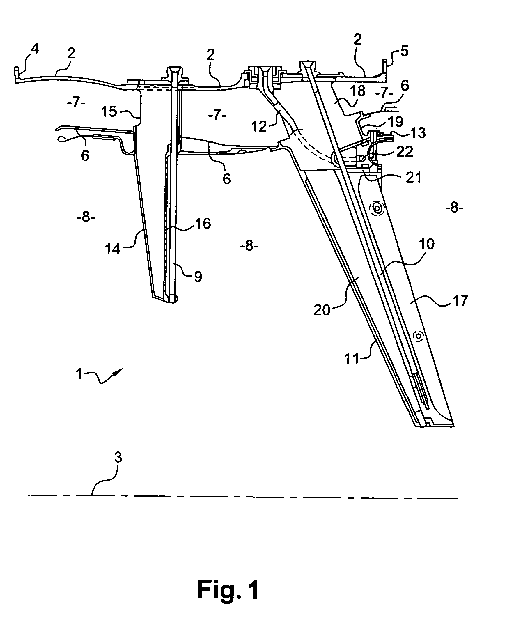
[0030]Reference is made initially to FIG. 1 showing part of an after-burner chamber 1 of a bypass turbojet, the chamber being located downstream from the turbine of the turbojet.

[0031]The after-burner chamber 1 comprises a substantially cylindrical outer casing 2 of axis 3 that has an outwardly-directed annular flange 4 at its upstream end for fastening to the outer casing of the turbine, and an outwardly-directed annular flange 5 at its downstream end for fastening to an outer casing of a nozzle.

[0032]The after-burner chamber 1 includes an inner annular casing 6 coaxial with the outer casing 2.

[0033]The outer surface of the inner casing 6 and the inner surface of the outer casing 2 define an annular space 7 extending from upstream to downstream, in which there flows the cold or secondary stream of the turbojet as generated by a fan at the upstream end of the turbojet and serving to increase thrust and to ventilate components of the turbojet.

[0034]The inner casing 6 defines a cylind...


PUM


Abstract

A device for fastening a fluid duct such as a fuel duct in an orifice of a turbojet casing, the device comprising a ring screwed into the orifice of the casing and having an annular rim coming to bear against a washer at the end of the duct, and a nut screwed onto the end of the duct so as to clamp the annular rim of the ring against the washer of the duct in order to fasten the duct to the casing.

Description

[0001]The present invention relates to a device for fastening a fluid duct to a turbojet casing, in particular a duct for feeding fuel to a burner ring in an after-burner chamber of the turbojet.BACKGROUND OF THE INVENTION[0002]In conventional manner, in a bypass turbojet having an after-burner chamber, a burner ring is mounted on the radially-outer ends of flame-holder arms which are themselves secured to the outer casing of the after-burner chamber, and a circular fuel injection duct extends inside the burner ring. The circular duct is connected at a plurality of points to fuel feeds on the outer casing of the after-burner chamber via feed ducts which extend radially between the outer casing and the burner ring. These feed ducts pass through the secondary stream of the turbojet that flows between the outer casing and an internal cylindrical wall defining the after-burner chamber where the burner ring is located and having flowing therein the primary flow formed by the exhaust gas ...

Claims


Application Information

Patent Timeline
Patent Type & Authority Patents(United States)
IPC IPC(8): F02K3/10F02K3/11F23R3/20F23R3/28
CPCF02K3/11F23R3/20F23R3/283
Inventor ROCHE, JACQUES ANDRE MICHELBUNEL, JACQUES MARCEL ARTHURRUELLAN, FREDERICHENRY, PHILIPPE PAUL MARIE
Owner SN DETUDE & DE CONSTR DE MOTEURS DAVIATION S N E C M A
Why Eureka
Try Eureka