
Method and system of providing clustered networks of bearing-measuring sensors

a technology of bearing-measuring sensors and clustering networks, applied in direction finders, navigation instruments, instruments, etc., can solve problems such as inability to use simple triangulation methods, difficulty in accurate generation of target location information, and line-of-site restrictions

Inactive Publication Date: 2008-05-13
HONEYWELL INT INC
View PDF4 Cites 15 Cited by
  • Summary
  • Abstract
  • Description
  • Claims
  • Application Information

AI Technical Summary

Problems solved by technology

Such line-of-site restrictions may arise with other conventional tracking systems, such as radar and / or optical systems.
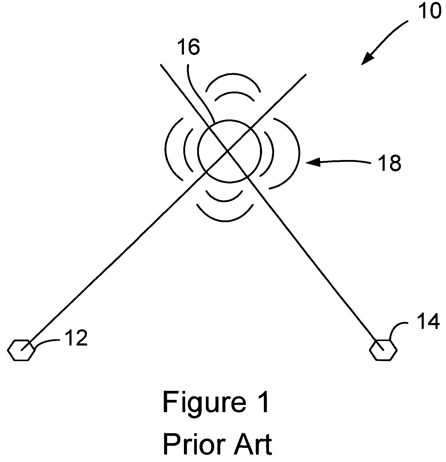
One concern with acoustic bearing sensors is that they possess a random bearing angle measurement error and therefore cannot be used with the simple triangulation method as illustrated in FIG. 1.
Consequently, accurate generation of target location information is difficult.
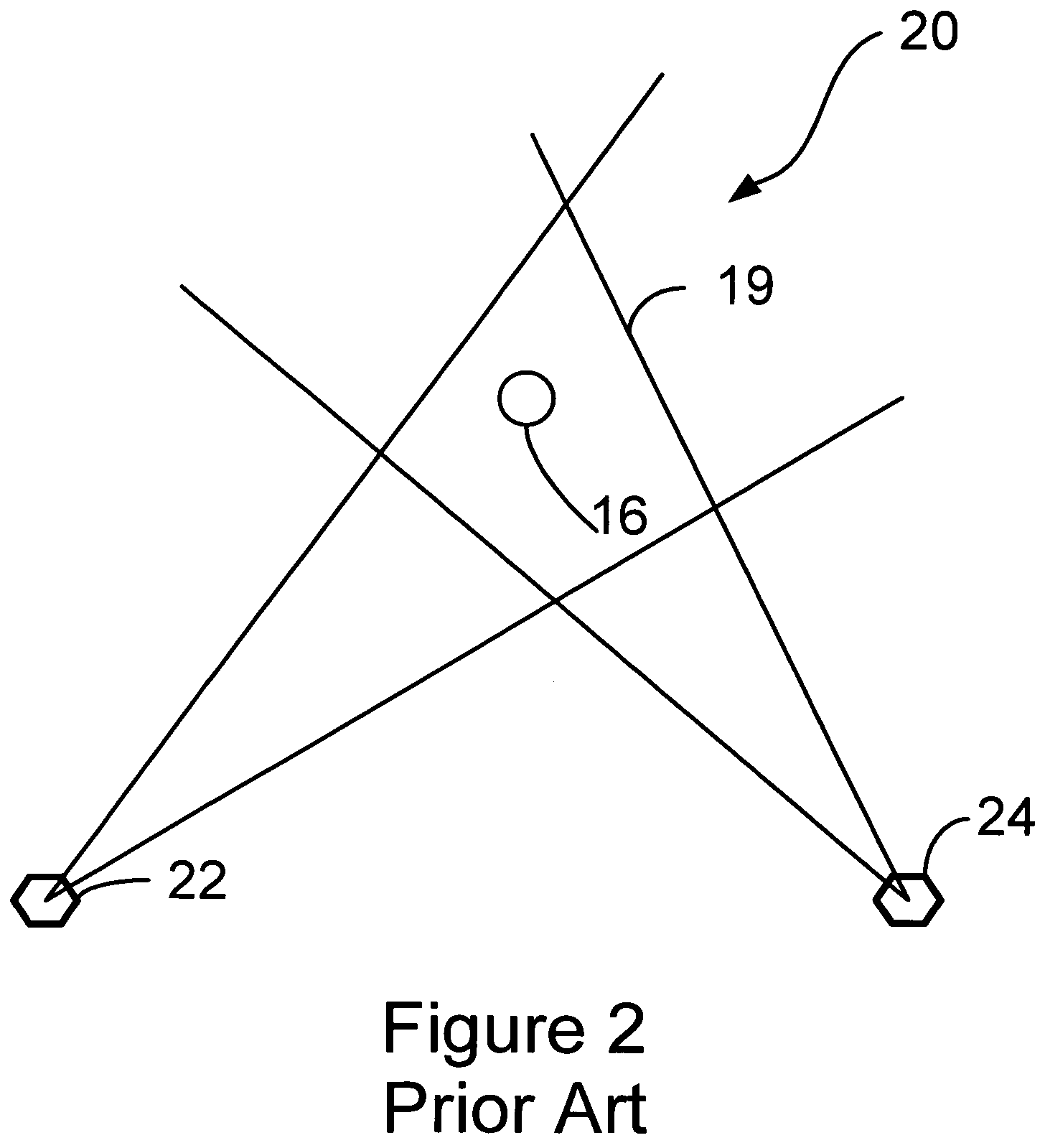
Consequently, depending on a distance between sensor and target, a large and therefore unacceptable uncertainty area 19 may be present.
Such a linear uncertainty on the order of almost 80 meters is considered too large of an uncertainty for certain applications, such as most target tracking applications since there may be a desire to intercept a target with a weapon and the weapon will miss the target if the target is substantially smaller than this uncertainty area.
Sub-optimal sensor geometry results in even larger linear errors, as do longer sensor-to-target distances.
Consequently, the errors in the direction where the uncertainty area is very long can be quite large, for example, several times the ±78.6 meter error estimate from above.
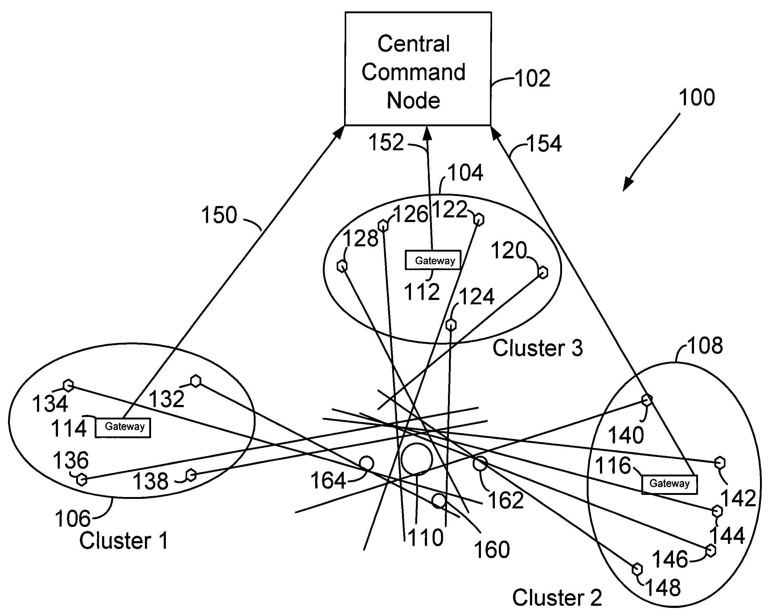
It is likely that this would result in wireless communication bottlenecks and not all sensor measurements would reach central computing node 70 in time for the once-per-second computation of the target location.
Such a centralized sensor network approach would also be more prone to failures when sensors or entire regions of the sensor network fail because the central computing node 70 would have to resolve these problems while possibly located many kilometers away from the location of the problem.

Method used


Image

  • Method and system of providing clustered networks of bearing-measuring sensors
  • Method and system of providing clustered networks of bearing-measuring sensors
  • Method and system of providing clustered networks of bearing-measuring sensors

Examples


Embodiment Construction

[0025]FIG. 4 illustrates a sensor 88 and a target 82 in an x-y coordinate system 80 and a bearing angle θ97 that sensor is designed to measure. Preferably, sensor 88 illustrated in FIG. 4 comprises a bearing measuring sensor, such as an acoustic bearing sensors illustrated in FIG. 1. An acoustic bearing sensor is one preferred type of sensor because it can detect vehicular targets that are up to two kilometers away and such sensors are generally inexpensive. Therefore, networks where a target is sensed by many sensors simultaneously (on the order of a few dozen to an order of a few thousand) can be generally practical from both a cost and logistics perspective. These types of sensors are also generally small devices (typically, on the order of 10 to 20 centimeters in diameter), are to be located on the ground, and comprise a small communications antenna and small batteries. Wireless communication range of such sensors is typically short and the communication bandwidth (“baud rate”) ...


PUM


Abstract

System and method for determining a location of a first target. The sensor network comprises a first sensor cluster comprising a first plurality of bearing measuring sensors. A first gateway is operatively coupled to the first plurality of bearing measuring sensors. A second sensor cluster comprises a second plurality of bearing measuring sensors. A second gateway is operatively coupled to the second plurality of bearing measuring sensors. A central command node is operatively coupled to the first and the second gateways. A first limited set of pre-computed numbers representative of information for generating a global target location estimation is transmitted from the first gateway to the central command node. A second limited set of pre-computed numbers representative of information for generating the global target location estimation is transmitted from the second gateway to the central command node. A global target location estimate of the first target is computed by the central command node based on the first and second limited set of pre-computed numbers.

Description

BACKGROUND[0001]1. Field of the Invention[0002]The present invention is generally directed to bearing measuring sensors. More particularly, the present invention is directed to methods and systems for providing at least one clustered network of bearing measuring sensors. The invention is particularly useful in utilizing at least one clustered acoustic bearing sensor network for estimating a target location. For example, the present invention may be used for estimating a target location of a ground or an airborne asset. However, aspects of the invention may be equally applicable in other scenarios as well.[0003]2. Description of Related Art[0004]Acoustic sensing technology can be used effectively by the various armed services of the United States of America for detecting and tracking ground and airborne assets. For example, acoustic sensing technology allows the acoustic sound emitted by ground vehicles, helicopters, aircraft and the like to be passively detected without certain line...

Claims


Application Information

Patent Timeline
Patent Type & Authority Patents(United States)
IPC IPC(8): G01S3/80
CPCG01C21/00G01S5/20
Inventor HORAK, DAN T.
Owner HONEYWELL INT INC
Learn More