Timing adjustment circuit and method thereof

a timing adjustment and circuit technology, applied in the direction of digital transmission, pulse automatic control, electrical equipment, etc., can solve the problems of time-consuming and laborious timing, inaccurate signal transmission, and inability to adjust the receiving or output timing, so as to achieve precise adjustment of receiving timing and accurate signal transmission

Active Publication Date: 2008-05-20
VIA TECH INC
View PDF2 Cites 1 Cited by
  • Summary
  • Abstract
  • Description
  • Claims
  • Application Information

AI Technical Summary

Benefits of technology

[0006]It is a primary object of the present invention to provide a timing adjustment circuit and method thereof that generate a plurality of sample clock signal by a multistage sample circuit to sample output signals of chips to generate a plurality of sampled signal. Finally, make comparison of the sampled signals to judge whether the received signals have errors or not. According to the comparison result, the receiving-end clock signal or output-end clock signal is adjusted to achieve the precise adjustment of receiving timing and output timing of chips as well as accurate signal transmission between two chips.

Problems solved by technology

The timing adjustment methods available now takes the time, cost and labors in trail and error.
However, it's timing consuming and labor intensive.
Moreover, the receiving or output timing may not be adjusted to the ideal values due to human errors and thus the signal transmission between chips is unstable.
And further the timing as well as accuracy of signal transmission between chips is affected.
In addition, the values of the receiving and output timing are fixed and are difficult to change.

Method used


Image

  • Timing adjustment circuit and method thereof
  • Timing adjustment circuit and method thereof
  • Timing adjustment circuit and method thereof

Examples


Embodiment Construction

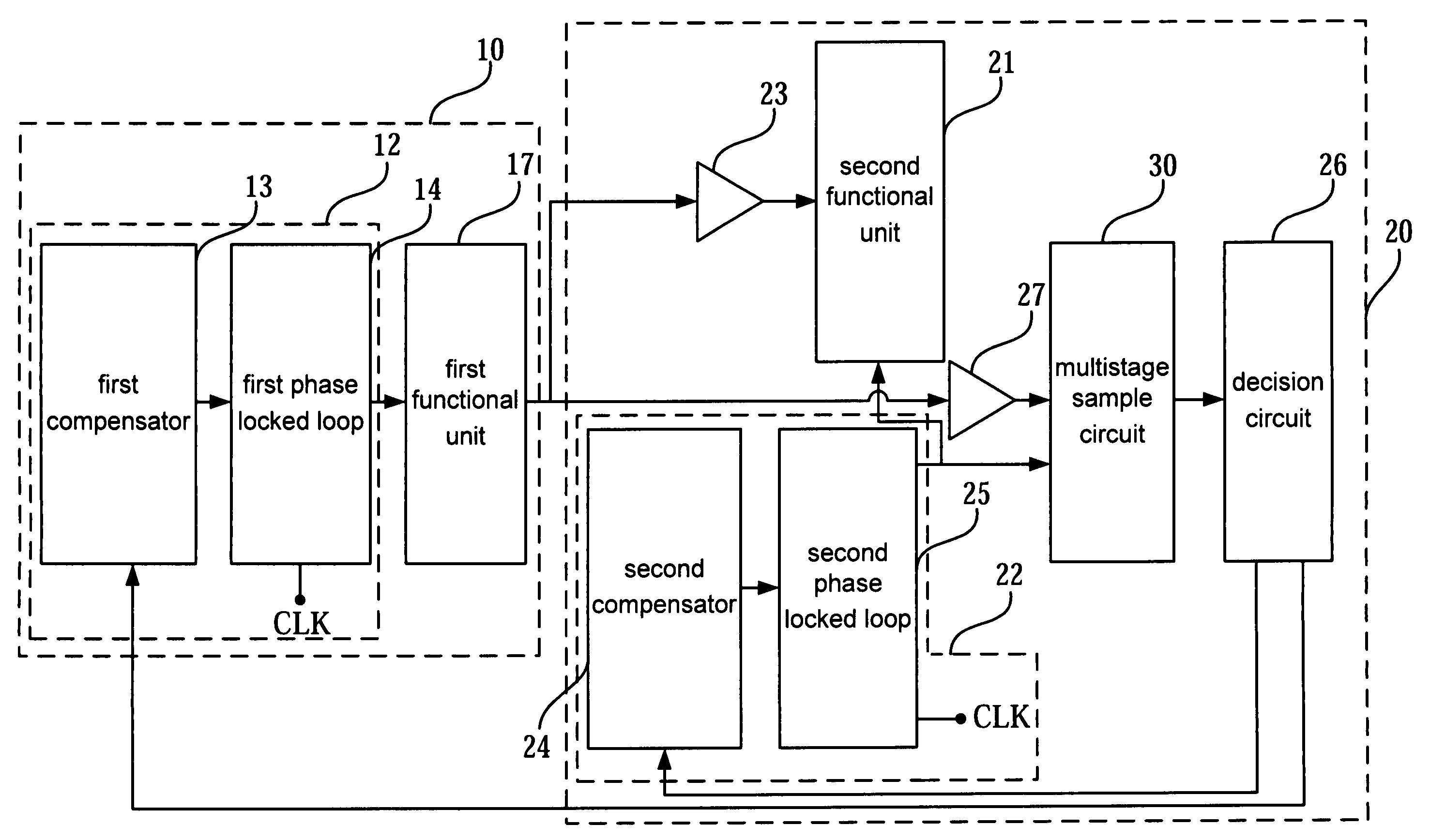
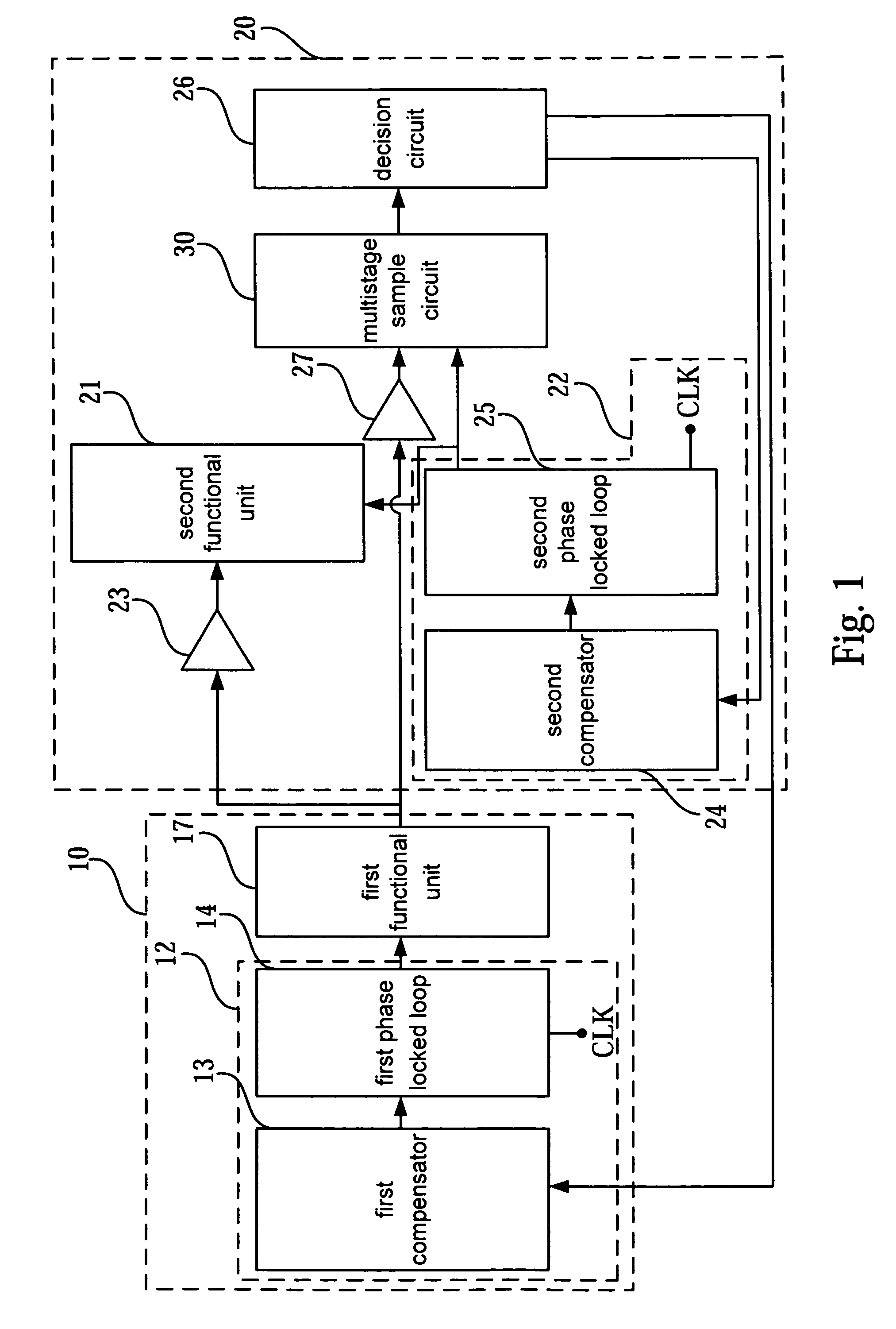
[0014]Referring to FIG. 1, which is the block diagram of an embodiment in accordance with the present invention. Before normal operation of a first chip 10 and a second chip 20, the embodiment adjusts timing in advance. More particularly, the receiving timing of an output signal transmitted from the first chip 10 and received by the second chip 20, and output timing of the output signal transmitted from the first chip 10 to the second chip 20 are adjusted in advance. So the adjustments make the signal transmission between the first chip 10 and the second chip 20 be precise after running of chips 10, 20. The first chip 10 is composed of a first timing adjustment unit 12 and a first functional unit 17. By receiving a base clock (CLK), the first timing adjustment unit 12 generates an output-end clock signal. According to the clock signal of the first timing adjustment unit 12, the first functional unit 17 transmits an output signal to a second functional unit 21 of the second chip 20. ...


PUM


Abstract

A timing adjustment circuit and method thereof are disclosed. The timing adjustment circuit at least consists of a second timing adjustment unit, a multistage sample circuit, and a decision circuit for adjusting received timing of an output signal transmitted by a first chip and received by a second chip. The method takes advantage of the multistage sample circuit to receive a clock signal of receiving end so as to generate a plurality of sample clock signal. Later, according to the sample clock signals, sample output signals to generate a plurality of sampled signal. At last, make comparison of the sampled signals by the decision circuit in accordance with the output signals to generate a second adjustment signal being transmitted to the second timing adjustment unit for adjusting phase of a base clock to generate an adjusted receiving-end clock signal. Thus the receiving timing of the second chip to receive the output signal is adjusted. Moreover, the decision circuit sends a first adjustment signal to a first timing adjustment unit of the timing adjustment circuit for generating an adjusted output-end clock signal. Thus the output timing that the first chip transmits the output signal to the second chip is adjusted.

Description

BACKGROUND OF THE INVENTION[0001]The present invention relates to an adjustment circuit and method thereof, especially to a timing adjustment circuit and method thereof for adjusting timing of transmitting signal as well as timing of receiving signal between chips so as to achieve precise signal transmission between chips and higher reliability of computer system.[0002]Most technical products available now are getting more powerful with compact volume and light weight. This is the result of chips with small size and enhanced performance. Due to high precision of chips, the signal transmission between chips is easy to get interference so that the signal transmission between chips as well as chip performance is also influenced. In order to provide more powerful functions, a single product generally integrates a plurality of chips, such as north bridge and south bridge, on motherboard. Therefore, precise signal transmission becomes one of the major research focuses on development of fu...

Claims


Application Information

Patent Timeline
Patent Type & Authority Patents(United States)
IPC IPC(8): H03L7/00
CPCH03L7/06H04L7/0004H04L7/0337
Inventor KUO, HUNG-YICHEN, HUI-MEI
Owner VIA TECH INC
Why Eureka
Try Eureka