Optical information recording medium containing a plurality of recording layers provided with characteristics to achieve optimum recording conditions

a technology of optical information and recording medium, which is applied in the field of optical information recording medium, optical information recording method and optical information recording apparatus, can solve the problems of non-uniform laser light used for recording information on the second information recording layer, inability to achieve accurate recording conditions, and inability to meet the requirements of recording conditions

Inactive Publication Date: 2008-05-20
PANASONIC CORP
View PDF8 Cites 47 Cited by
  • Summary
  • Abstract
  • Description
  • Claims
  • Application Information

AI Technical Summary

Problems solved by technology

However, conventional methods do not consider the following phenomenon.
Laser light used for recording information on the second information recording layer may become non-uniform when the laser light has passed through a certain area of the first information recording layer.
In this case, test recording would not provide accurate recording conditions.
As a result, accurate recording conditions are not obtained.
In this case also, information cannot be accurately recorded, which reduces the signal quality used for reproducing the recorded information.

Method used


Image

  • Optical information recording medium containing a plurality of recording layers provided with characteristics to achieve optimum recording conditions
  • Optical information recording medium containing a plurality of recording layers provided with characteristics to achieve optimum recording conditions
  • Optical information recording medium containing a plurality of recording layers provided with characteristics to achieve optimum recording conditions

Examples


example 1

[0067]This example relates to an optical information recording medium with which accurate recording conditions can be obtained by the test recording.

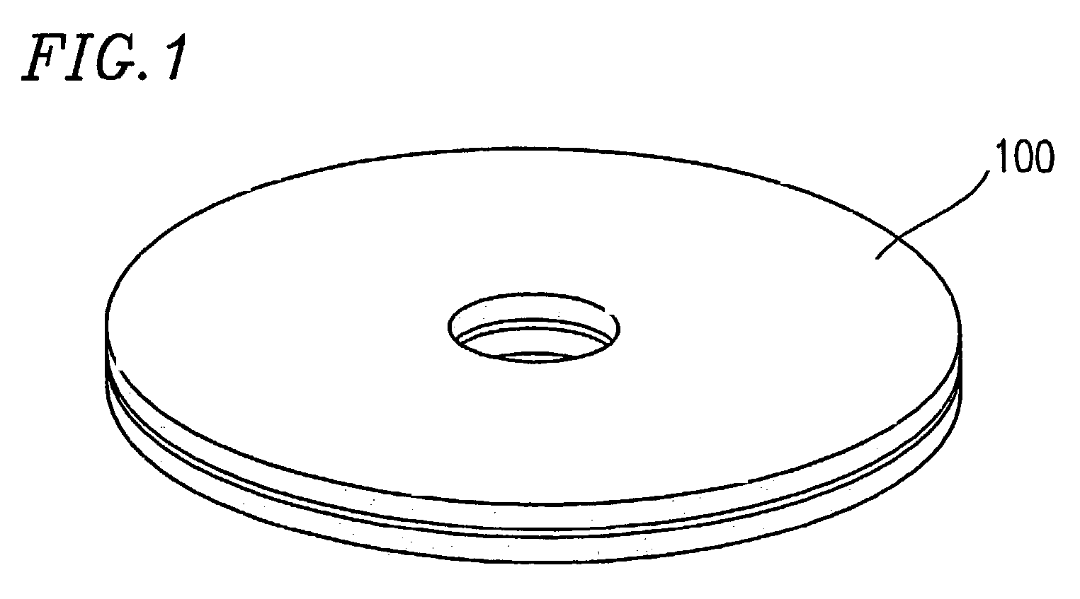
[0068]FIG. 1 is an external view of an optical information recording medium 100 according to the present invention. Hereinafter, the optical disc 100 will be used as a specific example of the optical information recording medium 100.

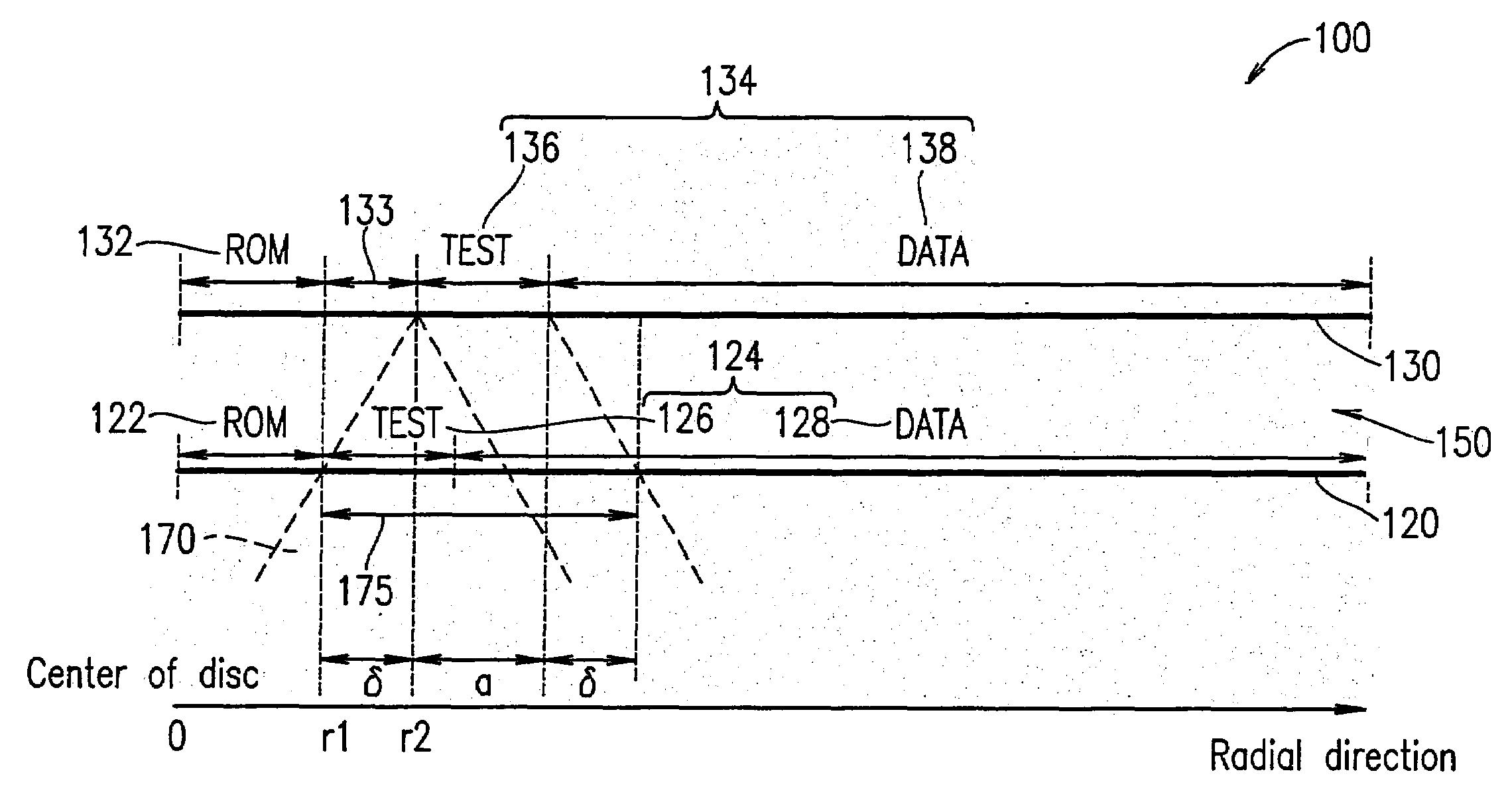
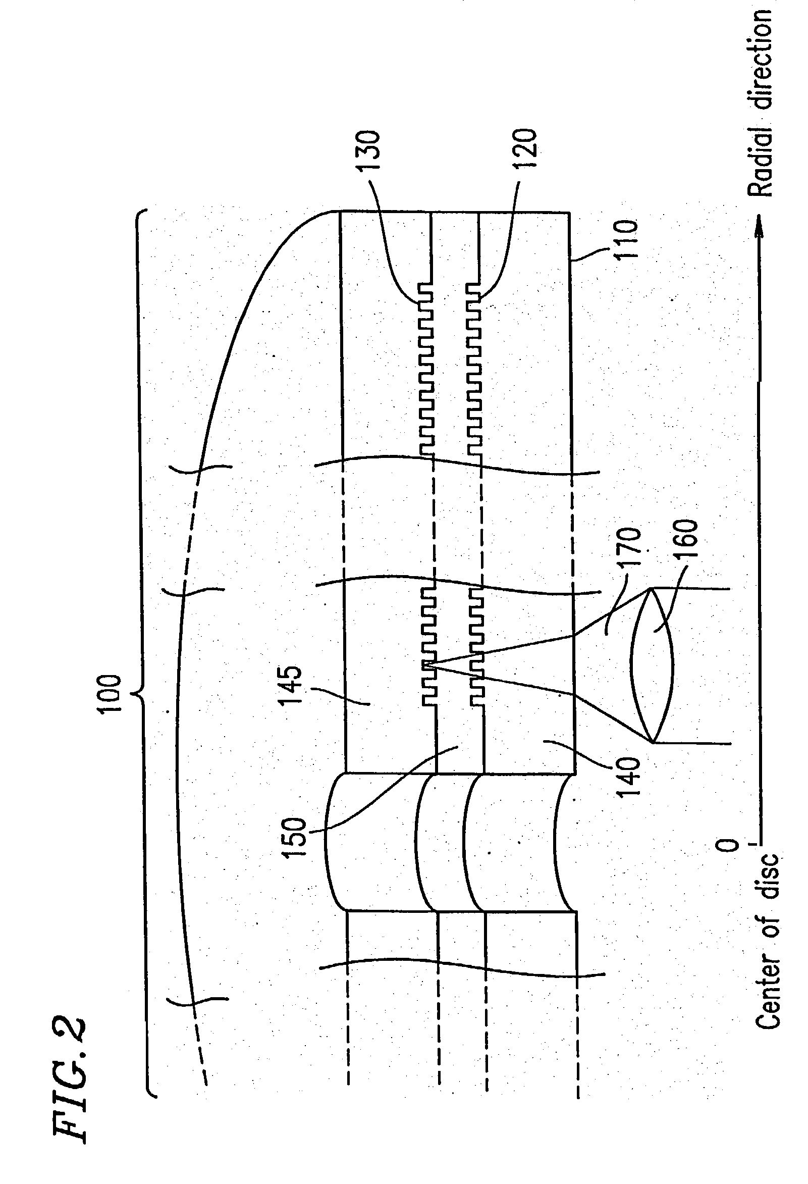
[0069]FIG. 2 is a cross-sectional view illustrating a structure of the optical information recording medium or the optical disc 100. The optical disc 100 has a multi-layer structure. As shown in FIG. 2, the optical disc 100 includes an incidence surface 110, a first information recording layer 120, a second information recording layer 130, and a separation layer 150 for separating the first information-recording layer 120 and the second information recording layer 130 from each other.

[0070]The first information recording layer 120 and the second information recording layer 130 are formed by pre-forming a gro...

example 2

[0108]In this example, a case where the center of the two information recording layers are offset with respect to each other will be described.

[0109]In actual production of a multi-layer recording medium, a plurality of information recording layers may be sometimes positionally offset with respect to each other when the information recording layers are bonded together. When the start points of the test recording areas are offset with respect to each other due to the positional offset between the information recording layers, the length δ considered in Example 1 is not sufficient. In this example, the effect of the present invention is provided even when the distances of the two information recording layers from the center of the disc are different from each other.

[0110]FIG. 7 shows a format of an optical disc 700 in which a first information recording layer 720 and a second information recording layer 730 are offset with respect to each other by δm.

[0111]The optical disc 700 include...

example 3

[0118]In this example, a case where the area of the first information recording layer, through which laser light used for recording information in the test recording area of the second information recording layer passes, is a recorded state area will be described.

[0119]FIG. 8 shows a format of an optical disc 800 according to this example.

[0120]The optical disc 800 includes a first information recording layer 820, a second information recording layer 830, and a separation layer 850 for separating the first information recording layer 820 and the second information recording layer 830 from each other.

[0121]The first information recording layer 820 includes a first reproduction-only area 822 and a first recording and reproduction area 824. The first recording and reproduction area 824 includes a first test recording area 826 and a first data recording area 828. In FIG. 8, the first information recording layer 820 includes the first reproduction-only area 822, the first test recording ...


PUM

PropertyMeasurementUnit
densityaaaaaaaaaa
optical constantsaaaaaaaaaa
transmittanceaaaaaaaaaa

Abstract

An optical information recording medium according to the present invention includes a first information recording layer on which information is to be recorded by laser light; and a second information recording layer on which information is to be recorded by the laser light which has passed through the first information recording layer. The first information recording layer includes at least one of a reproduction-only area and a recording and reproduction area. The second information recording layer includes a test recording area. At least one of the reproduction-only area and the recording and reproduction area, and the test recording area is located such that one of the reproduction-only area and the recording and reproduction area includes an area of the first information recording layer through which the laser light for recording information in the test recording area passes.

Description

TECHNICAL FIELD[0001]The present invention relates to an optical information recording medium, an optical information recording method and an optical information recording apparatus, for optically recording information. In more detail, the present invention relates to an optical information recording medium including a first information recording layer on which information is to be recorded by laser light and a second information recording layer on which information is to be recorded by the laser light which has passed through the first information recording layer; and a method and an apparatus for the optical information recording medium.BACKGROUND ART[0002]Recently, optical discs, optical cards, optical tapes and the like have been developed as optical information recording media for allowing information to be optically recorded. Among these, optical discs have attracted attention as optical information recording media for allowing a large capacity of information to be recorded at...

Claims


Application Information

Patent Timeline
Patent Type & Authority Patents(United States)
IPC IPC(8): G11B7/00G11B7/007G11B7/1267G11B7/24038
CPCG11B7/00736G11B7/1267G11B7/0953G11B2007/0013G11B7/007G11B7/24038
Inventor NARUMI, KENJINISHIUCHI, KENICHI
Owner PANASONIC CORP
Why Eureka
Try Eureka