
Fuel tank for straddle vehicle

a technology for straddling vehicles and fuel tanks, which is applied in the direction of transportation items, cycle equipment, cycle equipment, etc., can solve the problems of inability to design a larger fuel tank depth, inability to ensure the fuel tank is not occupied, and the space defined under the seat is inevitably small, so as to increase the degree of freedom of layout and facilitate the effect of ensuring the tank

Inactive Publication Date: 2008-05-27
YAMAHA MOTOR CO LTD
View PDF10 Cites 30 Cited by
  • Summary
  • Abstract
  • Description
  • Claims
  • Application Information

AI Technical Summary

Benefits of technology

The present invention is about improving the layout under the seat in a straddle type vehicle with a mono suspension structure. The invention provides a space behind the rear cushion unit under the seat to increase the degree of freedom for the layout. The fuel tank is positioned in a way that it does not interfere with the rear cushion unit or the rear wheel. The invention also includes an air cleaner and a battery that are disposed efficiently under the seat. The invention further includes a seat front cover that provides a space in front of the seat. Overall, the invention allows for better arrangement of vehicle components and improved performance.

Problems solved by technology

Thus, a space defined under the seat is inevitably small to restrict layout under the seat.
Also, in the motorcycle described above, the depth of the fuel tank cannot be designed to be larger because it is needed to ensure below the fuel tank a mount space for the rear cushion.
Thus, the layout under the seat is restricted by the large area size of the fuel tank in a top plan view.

Method used


Image

  • Fuel tank for straddle vehicle
  • Fuel tank for straddle vehicle
  • Fuel tank for straddle vehicle

Examples


Embodiment Construction

[0038]Hereunder, an embodiment of the present invention is described in detail, referring to the accompanying drawings.

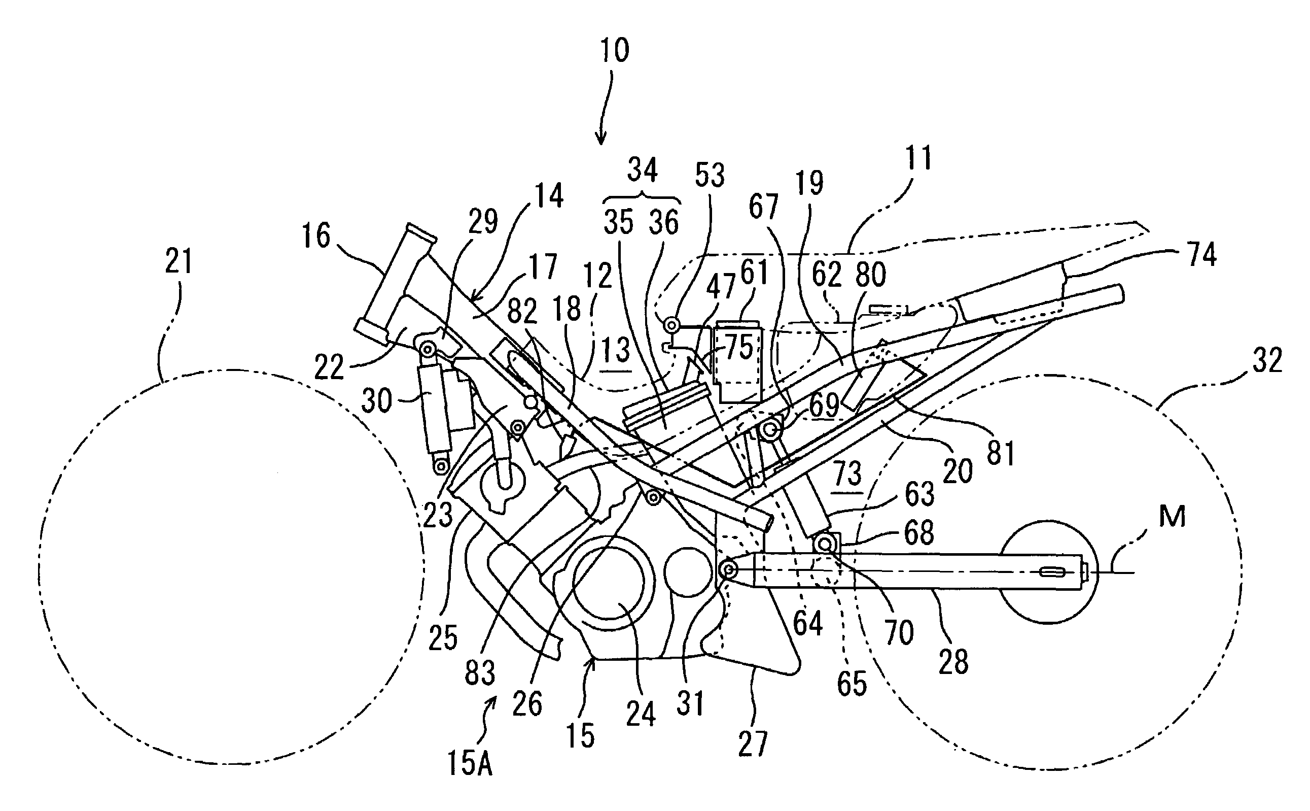
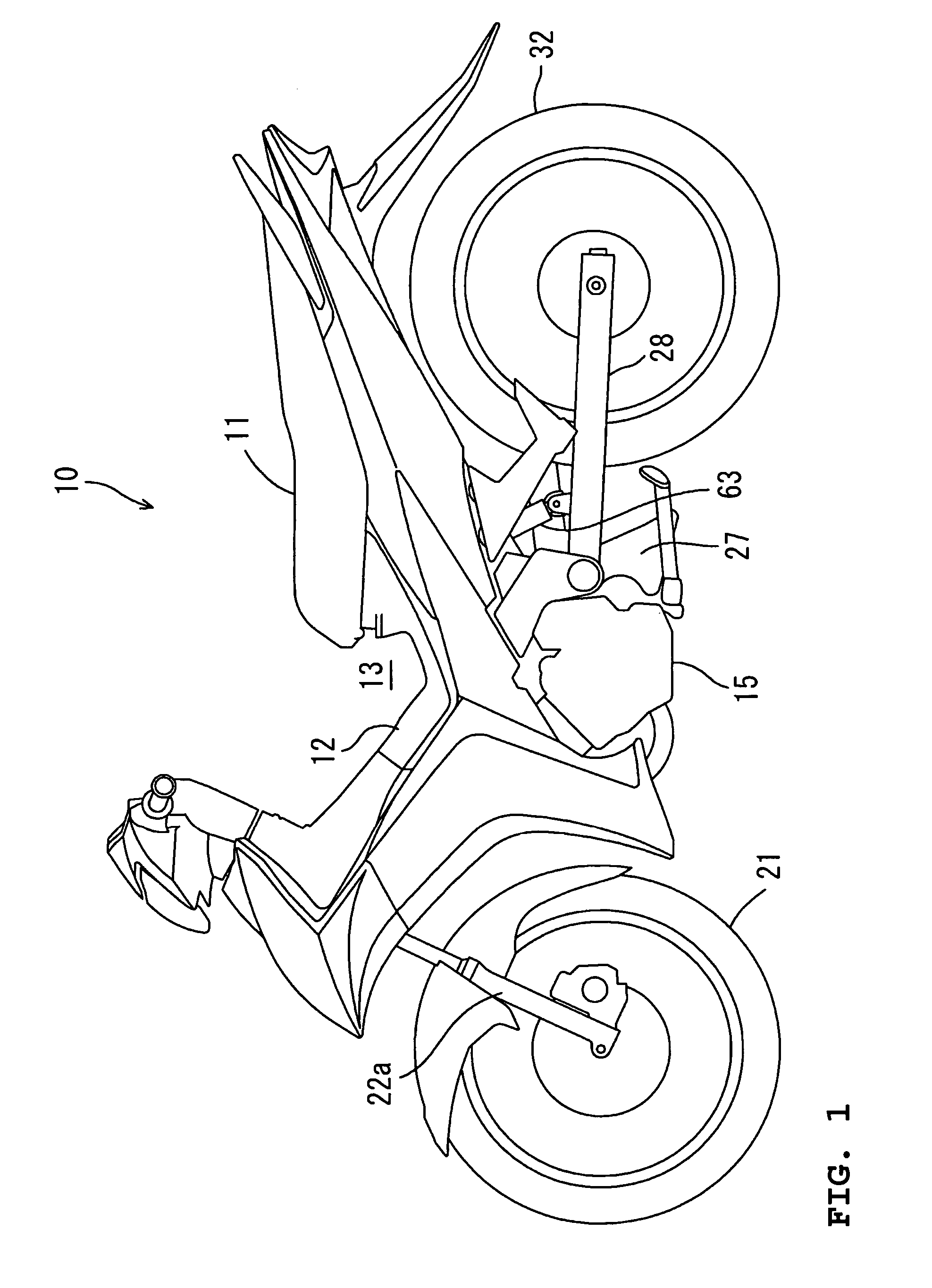
[0039]As shown in FIG. 1, a straddle type vehicle according to an embodiment is a motorcycle 10 having an under bone type frame structure. A detachable seat front cover 12 is attached below and ahead of a seat 11. The seat front cover 12 curves or bends to be a generally concave shape as seen in a side elevational view. The seat front cover 12 defines a space 13 that is recessed downward in front of the seat 11.

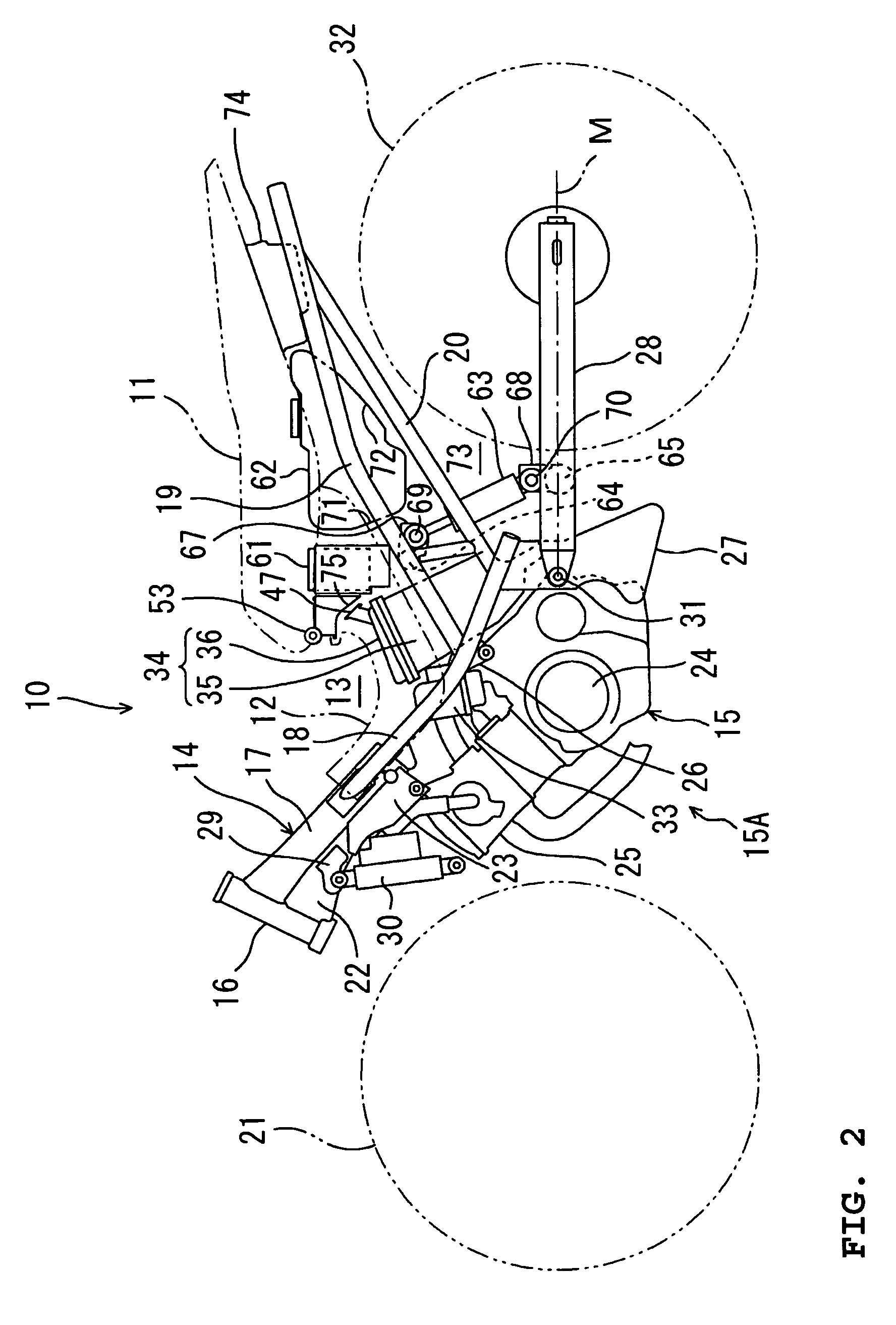
[0040]As shown in FIG. 2, the motorcycle 10 has a vehicle body frame 14, and an engine 15 supported by the vehicle body frame 14 under a suspended condition. The vehicle body frame 14 and the engine 15 together form a vehicle body 15A. The engine 15 includes a crankcase 24 and a cylinder block 25 obliquely extending upward forward from the crankcase 24. The vehicle body frame 14 includes a head pipe 16, a single main frame 17, a pair of a right and a left sub...


PUM


Abstract

A straddle vehicle includes a main frame obliquely extending downward and rearward from a head pipe. Right and left sub-frames obliquely extend downward and rearward from the main frame, and seat rails obliquely extend upward and rearward from the sub-frames. A cross member extends between the seat rails. A rear cushion unit is supported by the cross member and an upper portion of the rear arm and slants forward. A lower portion of a fuel tank projects downward to a space defined between the rear cushion unit and a rear wheel.

Description

BACKGROUND OF THE INVENTION [0001]1. Field of the Invention[0002]This invention relates to a straddle type vehicle such as a motorcycle, for example.[0003]2. Description of Related Art[0004]Conventionally, in straddle type vehicles such as motorcycles etc., some vehicles are known to include a structure that has a single rear cushion unit, i.e., the so-called mono suspension structure as a rear cushion unit (for example, see following Patent Document 1).[0005]The motorcycle disclosed in following Patent Document 1 includes a main frame obliquely extending downward rearward from a head pipe, and a pair of a right and a left seat rail obliquely extending upward rearward from a rear portion of the main frame. A fuel tank is mounted on the seat rails to be positioned under a seat. A rear wheel is supported by a rear end of a rear arm extending in a fore to aft direction. A front end of the rear arm is supported by a pivot shaft for swinging. A cross pipe extends between the right and le...

Claims


Application Information

Patent Timeline
Patent Type & Authority Patents(United States)
IPC IPC(8): B62K11/00B60P3/22B60R16/04B62J99/00
CPCB62J35/00B62K11/00B62K11/04
Inventor MIYABE, TOSHIMASA
Owner YAMAHA MOTOR CO LTD
Learn More