System for determining final position of teeth

a system and teeth technology, applied in the field of orthodontics, can solve the problems of time-consuming and expensive, tedious and painful process of attaching braces to teeth, and complicated process, and achieve the effect of satisfactory visual appearance of the model

Inactive Publication Date: 2008-05-27
ALIGN TECH
View PDF77 Cites 85 Cited by
  • Summary
  • Abstract
  • Description
  • Claims
  • Application Information

AI Technical Summary

Problems solved by technology

The process of attaching the braces to teeth is tedious and painful.
Additionally, each visit to the orthodontist is time consuming and expensive.
The process is further complicated by uncertainties in determining a final arrangement for each tooth.

Method used


Image

  • System for determining final position of teeth
  • System for determining final position of teeth
  • System for determining final position of teeth

Examples


Embodiment Construction

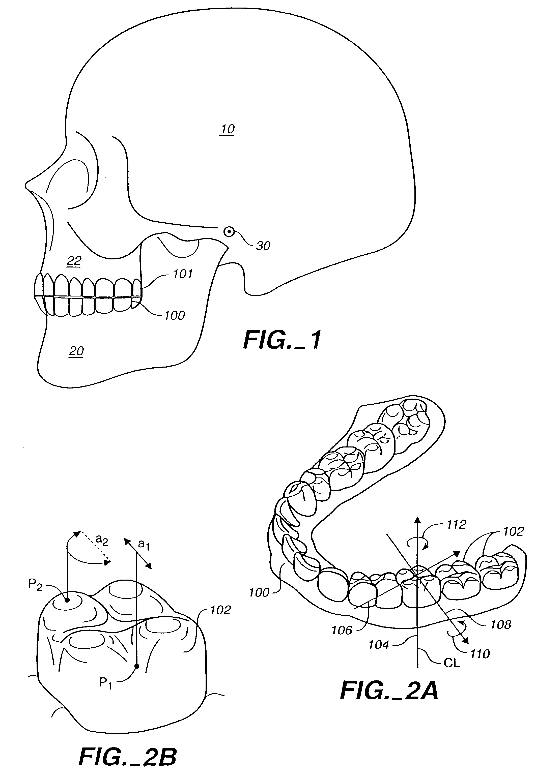
[0025]FIG. 1 shows a skull 10 with an upper jaw bone 22 and a lower jaw bone 20. The lower jaw bone 20 hinges at a joint 30 to the skull 10. The joint 30 is called a temporomandibular joint (TMJ). The upper jaw bone 22 is associated with an upper jaw 101, while the lower jaw bone 20 is associated with a lower jaw 100.

[0026]A computer model of the jaws 100 and 101 is generated, and a computer simulation models interactions among the teeth on the jaws 100 and 101. The computer simulation allows the system to focus on motions involving contacts between teeth mounted on the jaws. The computer simulation allows the system to render realistic jaw movements which are physically correct when the jaws 100 and 101 contact each other. The model of the jaw places the individual teeth in a treated position. Further, the model can be used to simulate jaw movements including protrusive motions, lateral motions, and “tooth guided” motions where the path of the lower jaw 100 is guided by teeth conta...


PUM


Abstract

An apparatus and method define a fit a set of upper and lower teeth in a masticatory system of a patient by generating a computer representation of the masticatory system of the patient; and determining an occlusion from the computer representation of the masticatory system using one or more keys.

Description

CROSS-REFERENCES TO RELATED APPLICATIONS[0001]This application is a continuation of U.S. patent application Ser. No. 10 / 047,078,filed Jan. 14, 2002, now U.S. Pat. No. 6,685,469 which was a continuation of application Ser. No. 09 / 313,291, filed May 13, 1999, now U.S. Pat. No. 6,406,292, which was a non-provisional of Application No. 60 / 110,189, filed Nov. 30, 1998. The full disclosures of the above applications are incorporated herein by reference.BACKGROUND OF THE INVENTION[0002]The present invention is related generally to the field of orthodontics, and more particularly to a system and a method for gradually repositioning teeth.[0003]A fundamental objective in orthodontics is to realign a patient's teeth to positions where the teeth function optimally and aesthetically. Typically, appliances such as braces are applied to the teeth of the patient by a treating orthodontist. Each appliance exerts continual forces on the teeth which gradually urge the teeth toward their ideal positio...

Claims


Application Information

Patent Timeline
Patent Type & Authority Patents(United States)
IPC IPC(8): A61C3/00A61C7/00A61C7/08A61C9/00A61C13/00G06F19/00
CPCA61C7/00A61C7/002G06F17/5009A61C9/0046A61C7/08A61C13/0004G16H50/50B33Y50/00B33Y80/00G06F30/20
Inventor CHISHTI, MUHAMMADBEERS, ANDREW
Owner ALIGN TECH
Why Eureka
Try Eureka