Light source coupler, illuminant device, patterned conductor, and method for manufacturing light source coupler

Inactive Publication Date: 2008-06-03
MORIYAMA SANGYO
View PDF28 Cites 85 Cited by
  • Summary
  • Abstract
  • Description
  • Claims
  • Application Information

AI Technical Summary

Benefits of technology

[0005]The present invention was made to solve the above prior art problems, and a primary object of the present invention is to provide a light source assembly comprising a p

Problems solved by technology

However, in a case that a variety of light emitting apparatuses having different light source arrangements and connection patterns are produced in small quantities, it can rather lead to a higher manufacturing cost.
Further, contact with the molten solder in the soldering process will expose the printed circuit board to a high temperature, and this is undesirable to LEDs, which can be easily damaged by heat.
Further, the solder typically contains lead, and thus the use thereof necessitates environmental measures.
It may be conceived to use a leadless solder, but the leadless solder is higher in price as well as in melting temperature, which can worsen the detrimental effects of heat against the LEDs.
Furthermore, the p

Method used


Image

  • Light source coupler, illuminant device, patterned conductor, and method for manufacturing light source coupler
  • Light source coupler, illuminant device, patterned conductor, and method for manufacturing light source coupler
  • Light source coupler, illuminant device, patterned conductor, and method for manufacturing light source coupler

Examples


Embodiment Construction

[0149]In the following, embodiments of the present invention are explained with reference to the drawings.

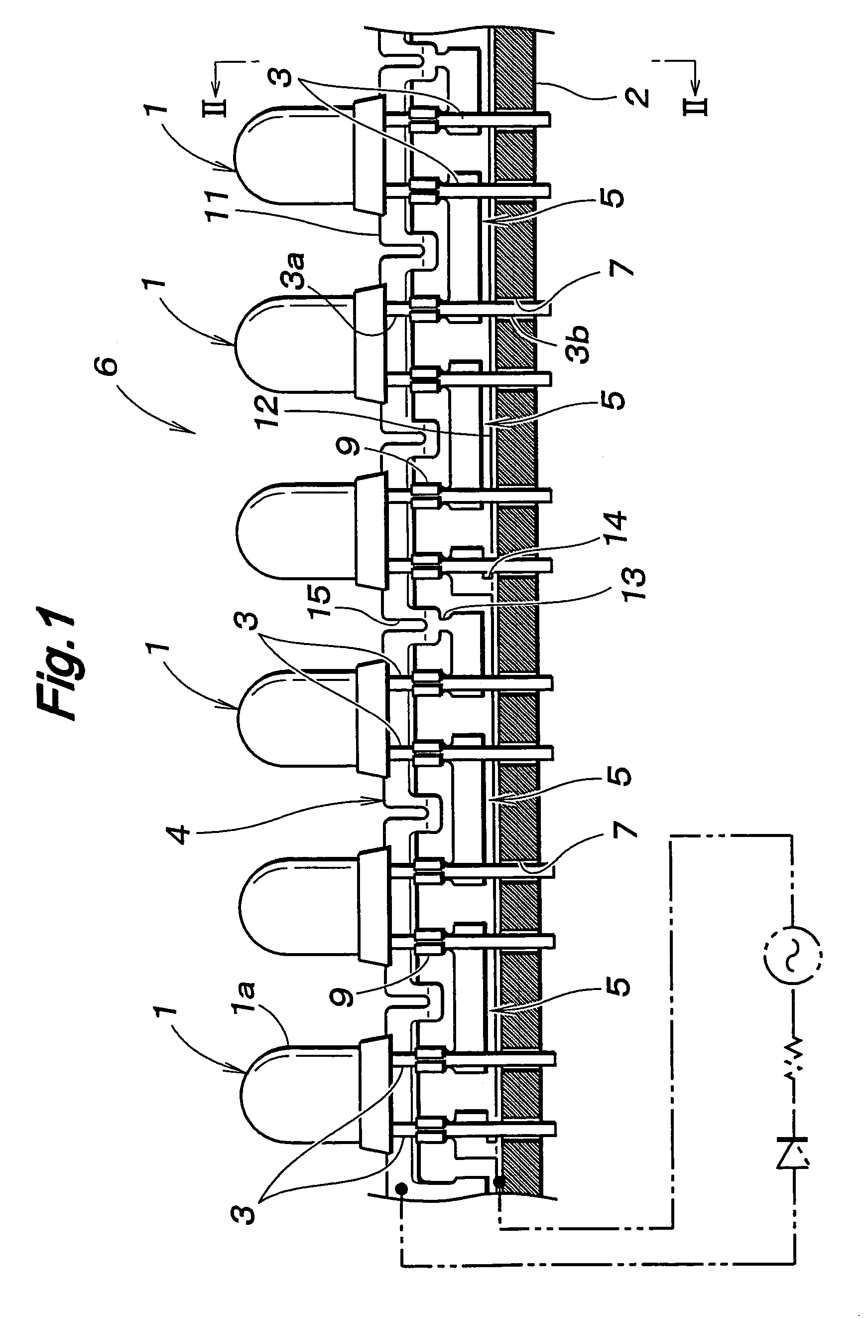
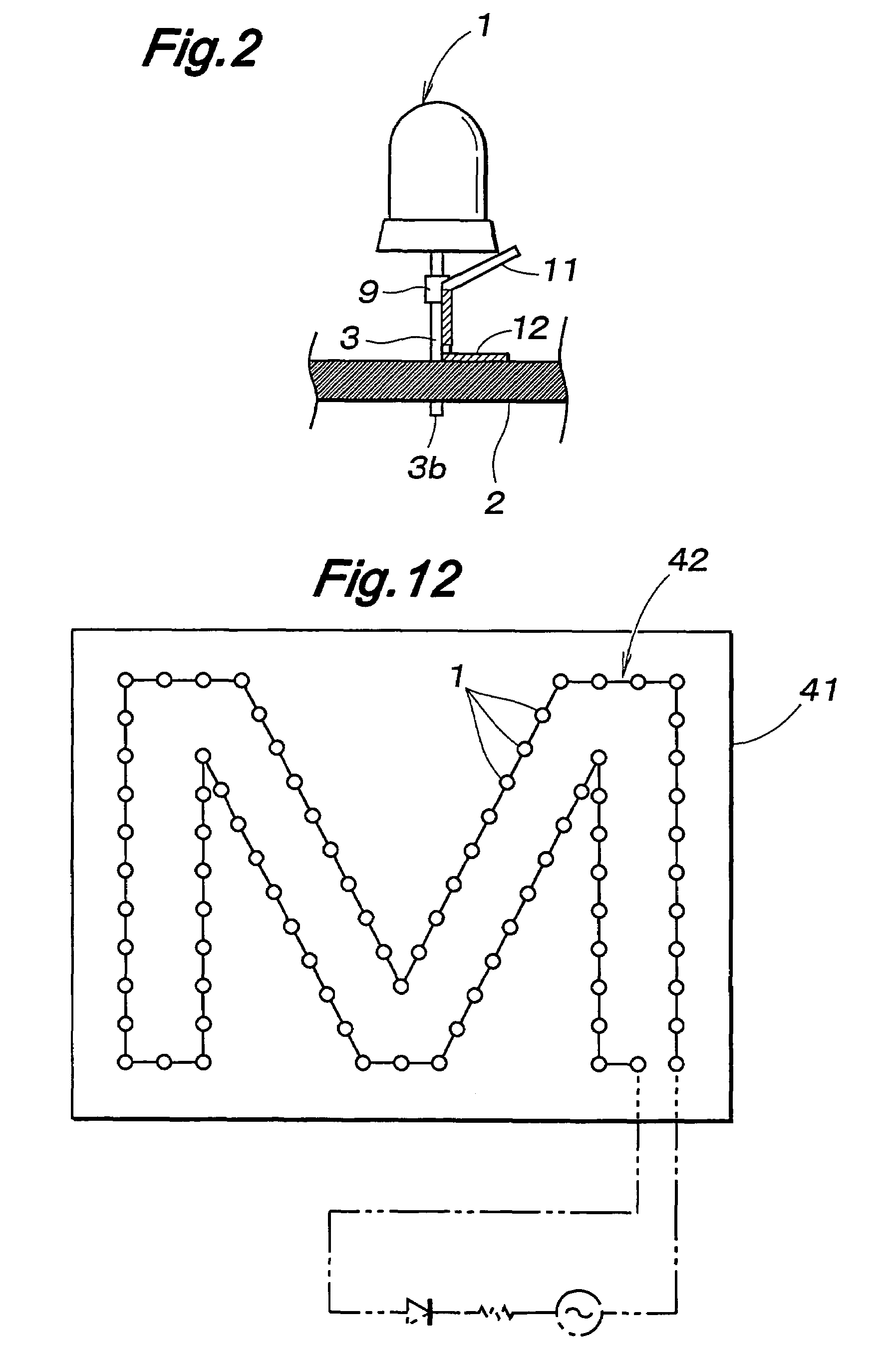
[0150]FIG. 1 is a front cross-sectional view showing a preferred embodiment of a light emitting apparatus according to the present invention. As shown, the light emitting apparatus comprises a plurality of light emitting diodes (LEDs) 1 as light sources, and each LED 1 consists of a bullet-type LED (or lamp-type LED) having a pair of parallel lead wires 3 functioning as electric connection terminals and a packaging part (or main body) 1a shaped like a bullet. The light sources 1 are arranged in a row along a surface of a mount board (holder) 2 in a direction perpendicular to the lead wires 3. The light sources 1 are series-parallel connected by a connective conductor structure 4 that extends in a direction of arrangement of the light sources 1, i.e., series connections of multiple light sources 1 are connected in parallel with each other, to form a light source assembly 6. The s...


PUM


Abstract

To provide a light source assembly that does not use a printed circuit board and can be manufactured at a low cost even when produced in small quantities, a light source assembly according to the present invention comprises a plurality of light sources and a connective conductor structure extending in a direction of arrangement of the light sources to join the light sources, wherein the connective conductor structure is formed by cutting off parts of a substantially plate-like patterned conductor as required, the patterned conductor being provided with a prescribed pattern. Thus, by changing the parts to be cut off in the patterned conductor, it is possible to manufacture light source assemblies having various light source connection patterns in a single manufacturing line, allowing efficient and low cost manufacture of the light source assemblies to be achieved even when the light sources are manufactured in small quantities.

Description

TECHNICAL FIELD[0001]The present invention relates to a light source assembly formed by electrically connecting a plurality of light sources, a light emitting apparatus using the light source assembly, a patterned conductor for forming the light source assembly and a method for forming the light source assembly.BACKGROUND OF THE INVENTION[0002]Light emitting apparatuses having a plurality of light sources arranged on a surface of a holder are used not only in general illumination but also in various usages such as advertisement, decoration, signaling and the like. In order to form such a light emitting apparatus, it may be conceived to use bullet-type LED light sources having lead wires and a printed circuit board formed with through-holes into which the lead wires of the light sources are inserted and a conductor pattern for transmitting electric power to the light sources, and to connect the lead wires of the light sources to the conductor pattern of the printed circuit board by m...

Claims


Application Information

Patent Timeline
IPC IPC(8): H01L23/495F21S4/00F21K99/00H05K1/00H05K3/20H05K3/32
CPCF21K9/17F21V19/0025F21Y2101/02F21Y2103/003H05K1/0286H05K3/202H05K3/326H01L2924/0002Y10S362/80H01L2924/00F21K9/27F21Y2103/10F21Y2115/10
Inventor MORIYAMA, HIDEOYANAGITA, MUNEHIKO
Owner MORIYAMA SANGYO
Why Eureka
Try Eureka