
Power supply apparatus for sliding structure

a technology for power supply apparatus and sliding structure, which is applied in the direction of insulated conductors, cables, conductors, etc., can solve the problems of unexpected breakage of power supply apparatus and corrugated tubes, and achieve the effects of preventing sound noise generation, preventing vibration, and facilitating slack

Inactive Publication Date: 2008-06-03
YAZAKI CORP
View PDF3 Cites 18 Cited by
  • Summary
  • Abstract
  • Description
  • Claims
  • Application Information

AI Technical Summary

Benefits of technology

The present invention provides a power supply apparatus for a sliding structure that prevents a wiring harness from penetrating into a car body when the sliding structure is opened half and reduces sound noise when the sliding structure closes an opening. The apparatus includes a base, a sliding structure, a wiring harness, and a limiting device. The limiting device is located at the wiring harness and is designed to limit its movement towards the base by abutting on an inner edge portion of the opening when the sliding structure positions between the close position and the open position. The wiring harness includes an electric wire, and the limiting device includes a mount portion and a projecting portion that allow it to abut on the inner edge portion of the opening. The tube body is formed into a bellows shape with alternated convex portions and concave portions along the lengthwise direction of the wiring harness, and the limiting device includes a plurality of separated member sets, at least one separated member set having a positioning projection to penetrate into the concave portion.

Problems solved by technology

Thereby, the corrugate tube may be caught by an object in the passenger room and the power supply apparatus may be broken unexpectedly.

Method used


Image

  • Power supply apparatus for sliding structure
  • Power supply apparatus for sliding structure
  • Power supply apparatus for sliding structure

Examples


Embodiment Construction

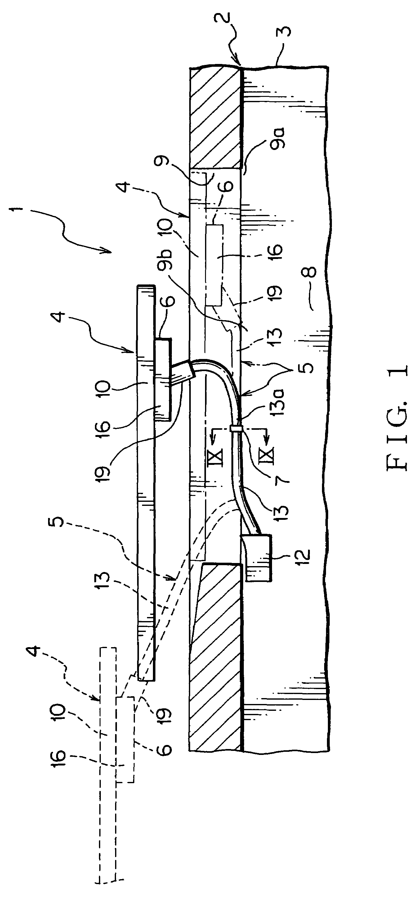
[0033]A power supply apparatus for a sliding structure (call power supply apparatus hereafter) of one embodiment according to the present invention will be described with reference to FIGS. 1-9.

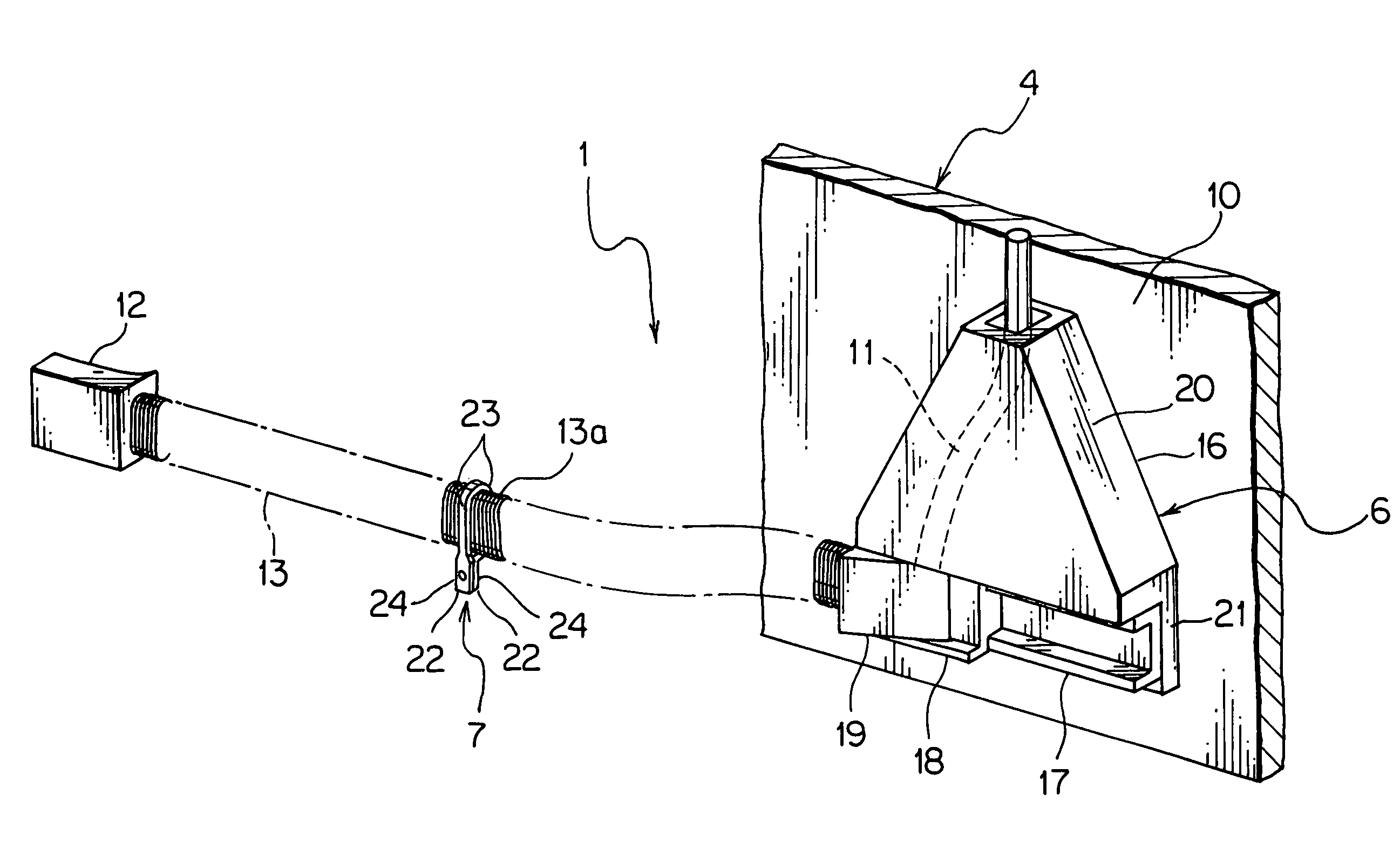
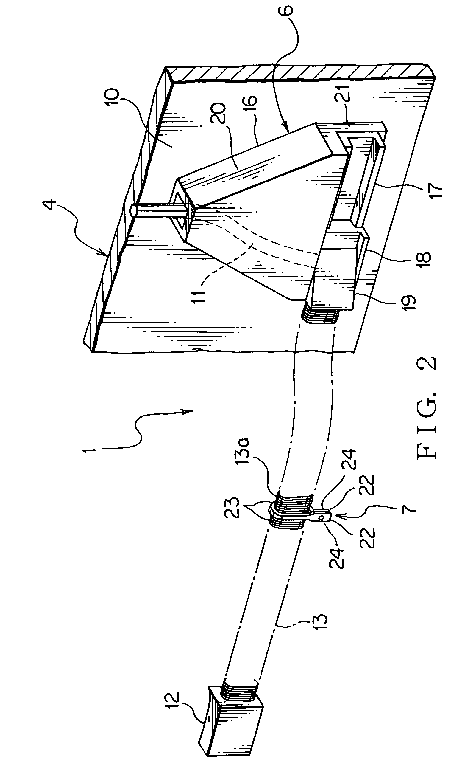
[0034]A power supply apparatus 1 includes a car body 3 as a base of a car 2, a sliding door 4 as a sliding structure mounted slidably on the car body 3, a wiring harness 5 wired between the car body 3 and the sliding door 4, a fixed portion 6 and a limiting device 7. The car body 3 has an opening 9, through which a passenger goes into and out from a passenger room arranged at a car main body 8 of the car 2. The opening 9 passes through a side wall of the car body 3.

[0035]The sliding door 4 is formed into a flat plate shape. The sliding door 4 has a door panel 10 made of sheet metal shown in FIGS. 2, 3. The sliding door 4 is supported slidably by a rail (not shown) mounted on the car body 3. The sliding door 4 is mounted slidably between a close position, in which the sliding door 4 closes the...


PUM

PropertyMeasurementUnit
electric poweraaaaaaaaaa
sound noiseaaaaaaaaaa
conductiveaaaaaaaaaa

Abstract

Providing a power supply apparatus for a sliding structure, which can prevent a wiring harness from penetrating into an opening when the sliding structure is opened half, and sound noise when the sliding structure is closed, the power supply apparatus for the sliding structure includes a car body, a sliding door mounted slidably on the car body, the wiring harness wired between the car body and the sliding door, a fixed portion and a limiting member. One end of the wiring harness is fixed at the car body. The other end of the wiring harness is fixed at the fixed portion, which is mounted on the sliding door. The limiting member abuts on a bottom edge of an inner edge of an opening.

Description

[0001]The priority application Number Japan Patent Application 2005-333408 upon which this patent application is based is hereby incorporated by reference.BACKGROUND OF THE INVENTION[0002]1. Field of the Invention[0003]This invention relates to a power supply apparatus for a sliding structure, which is mounted on the sliding structure such as, a sliding door of a vehicle for supplying continuously electric power to for example an auxiliary device at the sliding structure.[0004]2. Description of the Related Art[0005]A power supply apparatus 100 for a sliding structure (call power supply apparatus hereafter) shown in FIG. 10 for supplying continuously electric power to for an auxiliary device at a sliding door as the sliding structure of a vehicle is provided. The power supply apparatus 100 includes a car body 101 as a base, a sliding door 102 provided slidably on the car body 101 and a wiring harness 103 wired between the car body 101 and the sliding door 102.[0006]The car body 101 i...

Claims


Application Information

Patent Timeline
Patent Type & Authority Patents(United States)
IPC IPC(8): H01B7/06
CPCH02G11/006
Inventor NISHIJIMA, MASATAKAKISU, NAOMIMATSUO, TATSURO
Owner YAZAKI CORP
Learn More