Omniview motionless camera orientation system

a motionless camera and orientation system technology, applied in the field of capturing images, can solve the problems of inability to easily solve, distorted left and right ends of the final image, and only realizing the final image of the forest, and achieve the effect of accurate control and simple inputs

Inactive Publication Date: 2008-06-03
SONY CORP
View PDF90 Cites 172 Cited by
  • Summary
  • Abstract
  • Description
  • Claims
  • Application Information

AI Technical Summary

Benefits of technology

[0021]It is a further object of the invention to provide a spherical image capture system and method without the bulk of a large number of cameras and the necessity of multiple camera alignment.
[0043]The automatic printing or scanning technique creates the second hemispherical image (also known as a mirror image of the first image) through appropriate software. Alternatively, image processing software or hardware may reverse the scanned image without the need to manually flip a developed piece of film.

Problems solved by technology

Unfortunately, the ability of prior art systems to make the user feel part of the captured images are proportional to the cost of the image capture system.
The final image of the forest would then only be realized with the laborious task of manually cutting and pasting the different images together.
Unfortunately, the left and right ends of the final image become distorted and cannot be easily resolved.
Specifically, objects and relative distances near the extremes of the wide angle image become distorted.
Additionally, this approach wastes film.
However, scanning panoramic cameras invariably introduce noise into captured images through vibrations generated from their scanning motions as well as take a relatively long period of time to capture the image.
However, these screens are flat.
While this system offers significant improvements over a flat screen projection system, the viewer's absorption into the displayed images is limited by the edges of the displayed image.
However, as the number of cameras increase, the bulk of the imaging system likewise increases.
Using McCutcheon's system, increased resolution requires more bulk and more expense.
Furthermore, the images of each camera are not integrated together.
Accordingly, the system fails to account for the seams between the displayed images.
In the application where orientation of the camera and magnification of its image are required, the mechanical solution is large in size and can subtend a significant volume making the viewing system difficult to conceal or use in close quarters.
Collisions with the working environment caused by these mechanical pan / tilt orientation mechanisms can damage both the camera and the work space and impede the remote handling operation.
Also, these systems typically have no means of magnifying the image and or producing multiple images from a single camera.

Method used


Image

  • Omniview motionless camera orientation system
  • Omniview motionless camera orientation system
  • Omniview motionless camera orientation system

Examples


Embodiment Construction

Spherical Image Capture

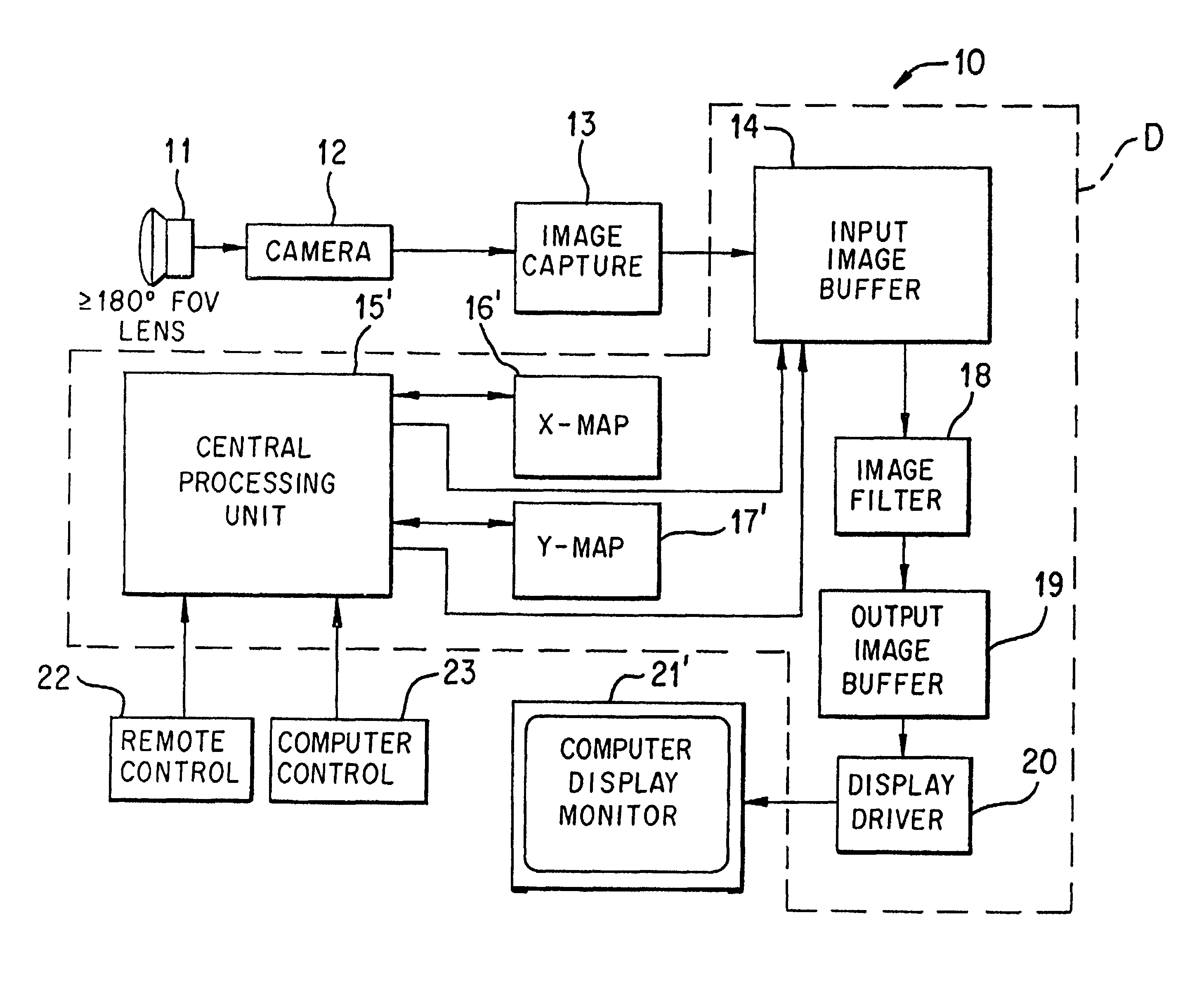
[0061]The disclosed Spherical Image Capture system employs the components disclosed in FIGS. 1-8 to capture hemispherical images and form spherical images. The image transform engine as disclosed in FIGS. 9-13 operates to transform selected portions of the formed spherical images into planar, perspective corrected portions.

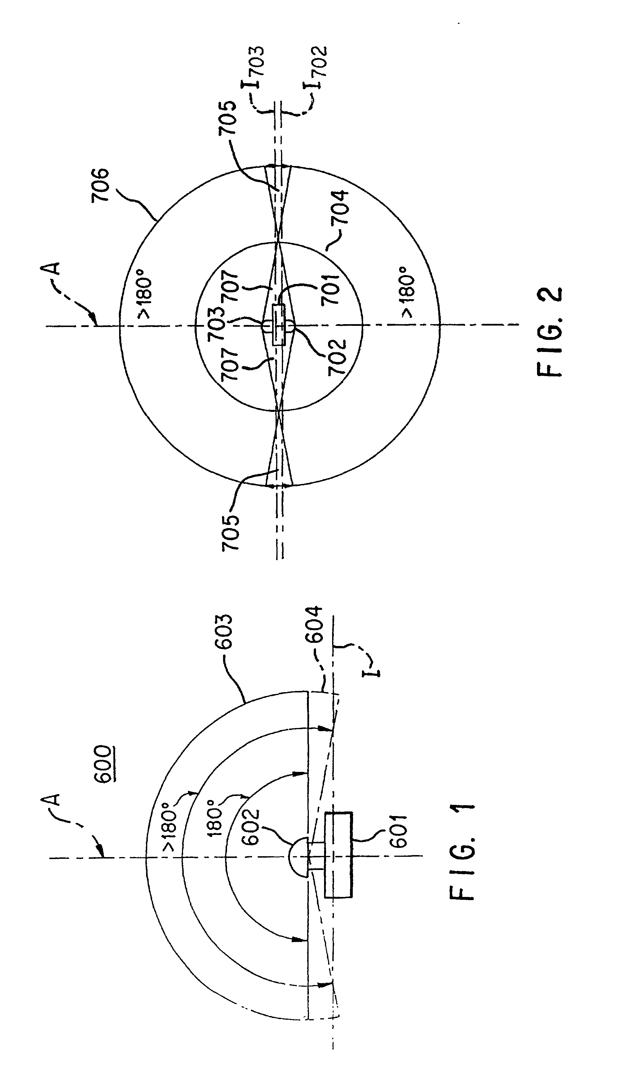
[0062]Referring to FIG. 1, camera 601 includes lens 602 with optical axis A, image plane I, and a field-of-view of 180° or greater. If lens 602 has a 180° field-of-view it captures at most the image from hemisphere 603. On the other hand, if lens 602 has a field-of-view greater than 180°, then it captures the image from sector 604 (shown by dotted lines) as well as that of hemisphere 603.

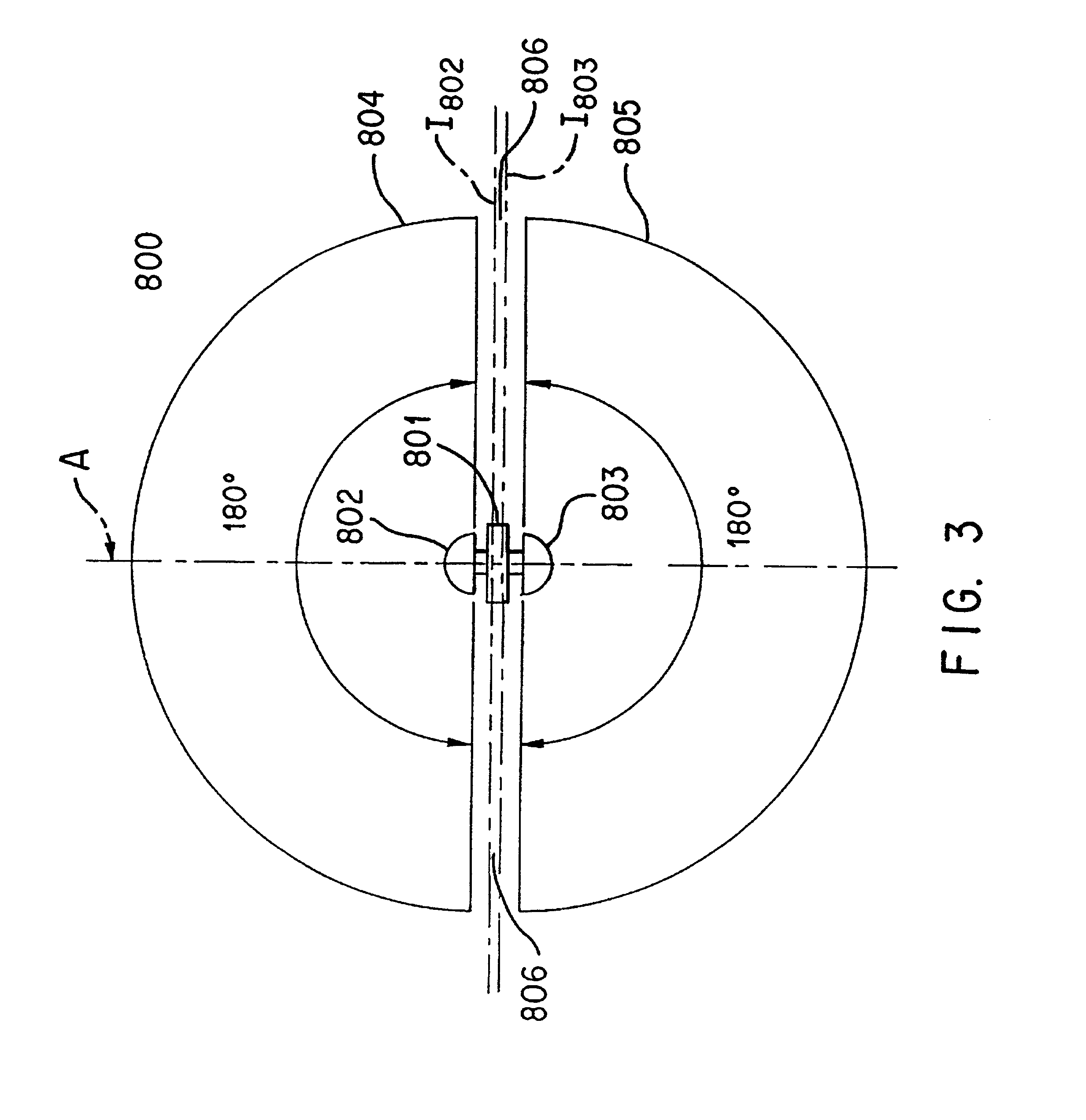
[0063]FIG. 2 shows a camera body 701 (which may include two cameras) connected to lenses 702 and 703 (with image planes I702 and I703, respectively). Each of lenses 702 and 703 have fields of view greater than 180°. Placed in a back-to-back arrangement where...


PUM


Abstract

A method and apparatus for capture of a spherical image is disclosed. The present invention includes at least one camera having a lens with at least a 180° field-of-view for capturing a hemispherical image. In a first embodiment, a second hemispherical image is created corresponding to a mirror image of the hemispherical image captured by the camera. In a second embodiment, two back-to-back cameras capture first and second hemispherical images, respectively. In both embodiments, a converter combines the two images along their outside edges to form a single, spherical image. Finally, the converter stores the complete spherical image for later retrieval and perspective corrected viewing.

Description

[0001]This application is a divisional of appl Ser. No. 08 / 863,584 filed May 27, 1997 now U.S. Pat. No. 6,002,430 which is a continuation-in-part of U.S. application Ser. No. 08 / 386,912 filed Feb. 8, 1995 now abandoned, which is a continuation of U.S. application Ser. No. 08 / 339,663 filed Nov. 14, 1994 now abandoned, which is a continuation of U.S. application Ser. No. 08 / 189,585 filed Jan. 31, 1994 (now U.S. Pat. No. 5,384,588), which is a continuation-in-part of U.S. application Ser. No. 08 / 014,508 filed Feb. 8, 1993 (now U.S. Pat. No. 5,359,363), which is a continuation-in-part of U.S. application Ser. No. 07 / 699,366 filed May 13, 1991 (now U.S. Pat. No. 5,185,667). This application is also a continuation-in-part of U.S. application Ser. No. 08 / 373,446 filed Jan. 17, 1995, which is a continuation-in-part of U.S. application Ser. No. 08 / 189,585 filed Jan. 31, 1994 (now U.S. Pat. No. 5,384,588).[0002]This invention was made with Goverment support under contract NAS1-18855 awarded b...

Claims


Application Information

Patent Timeline
Patent Type & Authority Patents(United States)
IPC IPC(8): H04N5/30
CPCH04N5/2254H04N5/2259H04N23/58H04N23/698
Inventor MCCALL, DANNY A.MARTIN, H. LEE
Owner SONY CORP
Why Eureka
Try Eureka