
Computer user interface for interacting with video cliplets generated from digital video

Inactive Publication Date: 2008-06-03
MICROSOFT TECH LICENSING LLC
View PDF9 Cites 93 Cited by
  • Summary
  • Abstract
  • Description
  • Claims
  • Application Information

AI Technical Summary

Benefits of technology

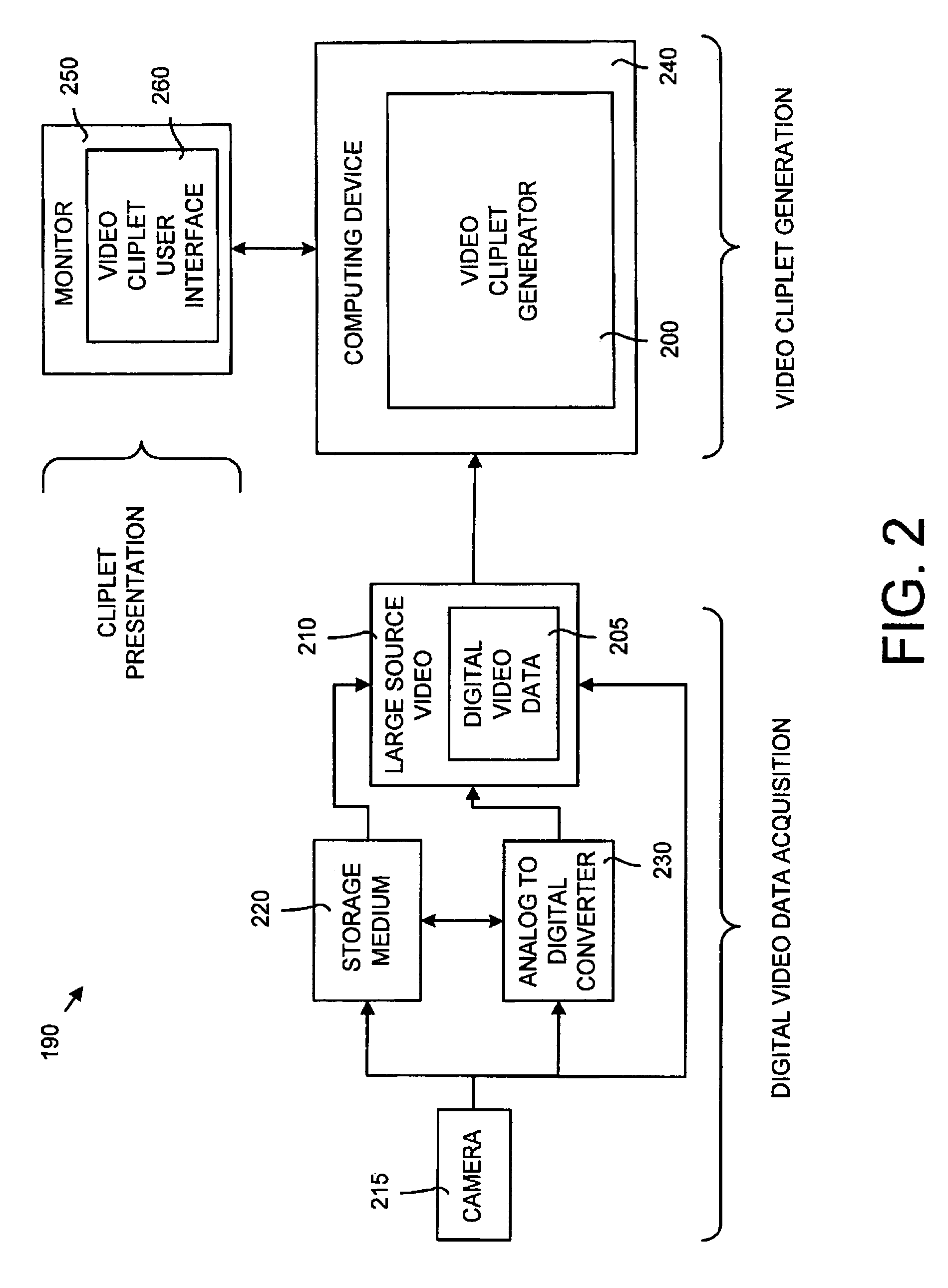
[0009]The invention disclosed herein includes a computer user interface system and a method for displaying short segments of video each representing a single event or theme (called video cliplets or “cliplets”). The cliplets are generated from longer units of video (or a source video) by automatically determining editing points and extracting the cliplets from the source video using the editing points. The computer user interface displays the cliplets and information and properties of each of the cliplets. In this manner, a user can quickly and easily determine information about the source video, such as the subject matter contained on the video and the interesting portions.
[0010]The cliplet user interface system and method of the invention overcomes the problems of the traditional editing software by using cliplets to divide a larger source video into smaller segments. Rather than displaying only one or two views of the source video, the cliplet user interface displays a multitude of views of the source video by presenting a plurality of cliplets to a user. In addition, information about each cliplet is displayed to the user to make editing with cliplets even easier for the user. The cliplets are pre-cut from the source video, eliminating the need for the user to manually scrub the source video to determine good editing points. Moreover, editing of the source video occurs using the cliplets rather than long, tedious stretches of video.

Problems solved by technology

Moreover, editing of the source video occurs using the cliplets rather than long, tedious stretches of video.

Method used


Image

  • Computer user interface for interacting with video cliplets generated from digital video
  • Computer user interface for interacting with video cliplets generated from digital video
  • Computer user interface for interacting with video cliplets generated from digital video

Examples


working example

V. Working Example

[0063]FIG. 7 is a working example of the cliplet user interface 460 shown in FIG. 6. It should be noted that this is only one way in which the cliplet user interface 260 may be implemented. FIG. 7 includes a thumbnail user interface 700 that is an example of the cliplet user interface 260. The thumbnail user interface 700 includes a cliplet area 710 that is displaying thirty-four cliplets numbered #0 to #33. Each one of the cliplets is displayed in a thumbnail window 715, and each cliplet is represented by a thumbnail image in the thumbnail window 715. Adjacent to the thumbnail window 715 is a cliplet interest ratings area 718 that displays interest rating information as described below.

[0064]A cliplet video window 720 is used to play a desired cliplet. A “Play Until Stopped” feature 725 can be selected by a user to instruct the cliplet video window to play from the point shown in the window 720 (usually the keyframe or thumbnail representing the cliplet) until the...


PUM


Abstract

The present invention includes a computer user interface system and a method for displaying short segments of video each representing a single theme or event (called video cliplets or “cliplets”). The computer user interface displays the cliplets and information and properties of each of the cliplets. Through the computer user interface of the invention, a user can quickly and easily determine the contents and interesting portions of the video. The cliplet user interface method includes displaying a plurality of cliplets in a two-dimensional arrangement along with cliplet information. The cliplet user interface system includes a plurality of keyframe windows for displaying cliplets and a keyframe within each keyframe window representing a cliplet therein. Moreover, the cliplet user interface system includes a cliplet property presentation area for displaying a cliplet interest rating. The cliplet interest rating indicates the amount of interesting content within the cliplet for a particular cliplet property.

Description

TECHNICAL FIELD[0001]The present invention relates in general to a computer user interface and more particularly to a system and a method for displaying short segments of video (or video “cliplets”) and information and properties about the cliplets using a computer user interface.BACKGROUND OF THE INVENTION[0002]Video cameras (or camcorders) are devices that are popular with amateur videographers. Video cameras may be a digital camera, which stores digital video on a memory device, or an analog video camera, which stores video footage on magnetic videotape. Video footage captured by an analog video camera may be converted into a digitized format using well-known techniques. Digital video may be processed using a software running on a computing devices (such as personal computers) to edit and manipulate the data captured by video cameras.[0003]The traditional home digital video paradigm expects a user to shoot good video, perform tedious video editing, and then output a single large ...

Claims


Application Information

Patent Timeline
IPC IPC(8): G06F3/048G06F3/01G06F3/14H04N5/91G06F3/033G06F17/30G11B27/034G11B27/28G11B27/34H04N5/14H04N5/45
CPCG06F3/0481H04N21/8456G06F17/30849G11B27/034G11B27/28G11B27/34H04N21/4143H04N21/4312H04N21/4314H04N21/4316H04N21/4394H04N21/44008H04N21/440263H04N21/44222H04N21/47217H04N21/8173H04N21/84G06F17/30787H04N5/147H04N5/45H04N21/4223H04N21/4786G06F16/743G06F16/7834
Inventor TOYAMA, KENTARODRUCKER, STEVEN M.
Owner MICROSOFT TECH LICENSING LLC
Learn More