Apparatus and methods for pumping high viscosity fluids

a technology of high viscosity fluids and apparatus, which is applied in the field of apparatus and methods for pumping high viscosity fluids, can solve the problems of unavoidable introduction of small air bubbles, inability to achieve optimal venting, and corresponding undesirable contamination of fluids, so as to facilitate the use of the system, improve performance and benefits, and simplify the flow path

Inactive Publication Date: 2008-06-10
ENTEGRIS INC
View PDF102 Cites 63 Cited by
  • Summary
  • Abstract
  • Description
  • Claims
  • Application Information

AI Technical Summary

Benefits of technology

[0024]An additional object of the invention is the provision of integrated circuits, chips, or other microelectronic devices fabricated from the aforementioned apparatus or methods.

Problems solved by technology

In certain applications, that path does not afford optimal venting for any contaminating air bubbles that may become entrapped in the fluid or the system.
For example, some small amount of air bubbles may be unavoidably introduced when the source fluid container is periodically changed, even if no re-priming is required.
Portions of the flow path that are metal or otherwise relatively potentially contaminating result in some risk (however small) of corresponding undesirable contamination of the fluid.
As indicated in those prior patents, such bubbles or contaminants could potentially compromise the end product to some degree in some small percentage of applications.
Alternatively, such bubbles or contaminants might require some period of “flushing” bubbles from the system upon changing the source fluid container, for example, or might otherwise compromise the accuracy of the fluid dispense system (again, in a small percentage of applications and situations).
Additionally, reducing and realigning the fluid flow path can reduce the size of the “footprint” for the housing of the system and otherwise make the system more compact as compared to prior art systems, thereby correspondingly reducing valuable factory space for the users of the pump system.

Method used


Image

  • Apparatus and methods for pumping high viscosity fluids
  • Apparatus and methods for pumping high viscosity fluids
  • Apparatus and methods for pumping high viscosity fluids

Examples


Embodiment Construction

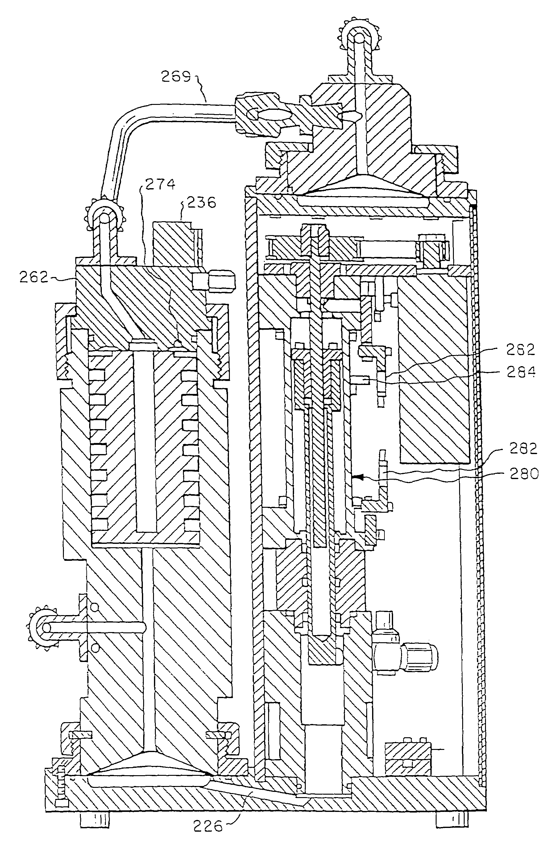
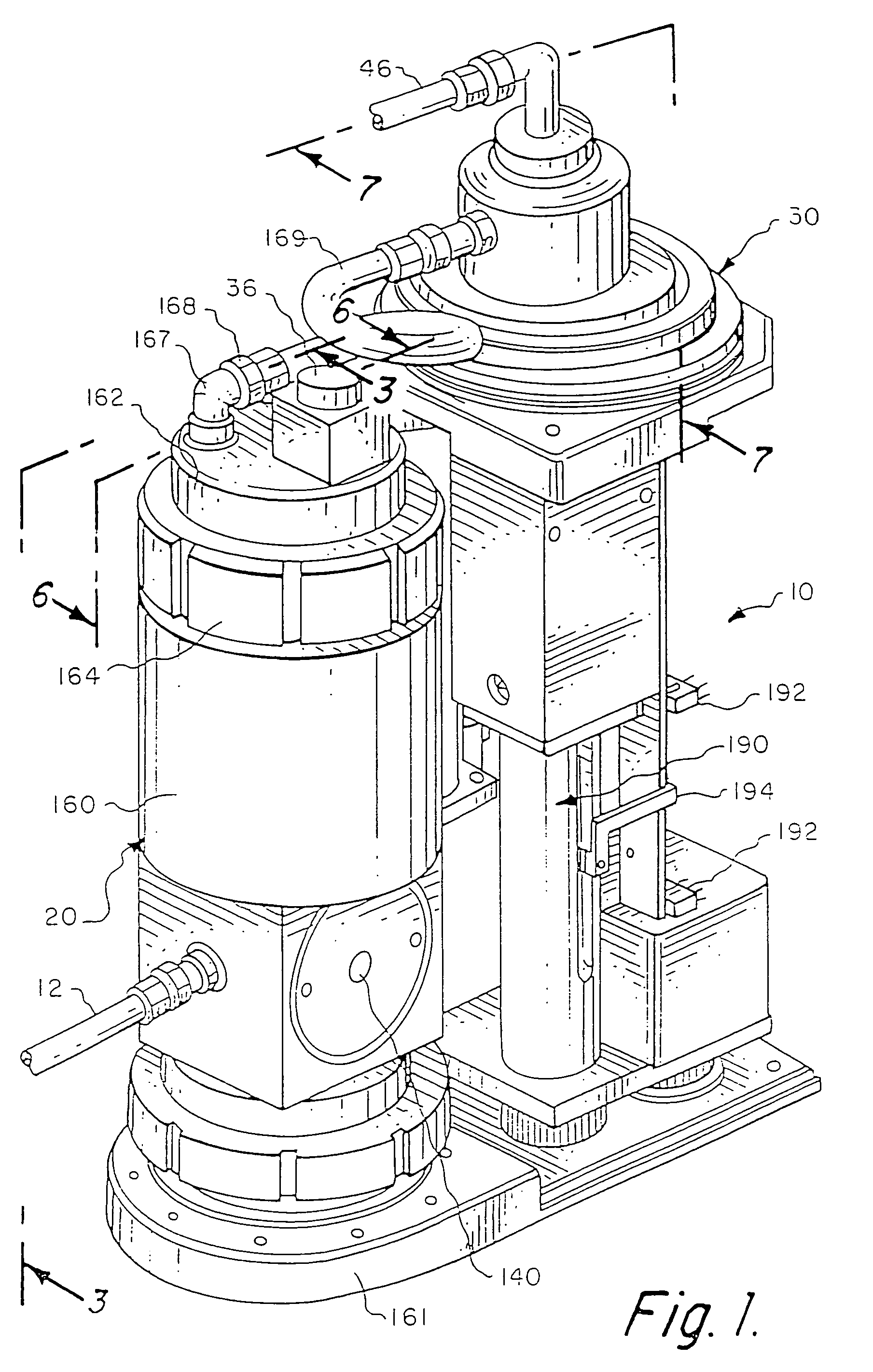
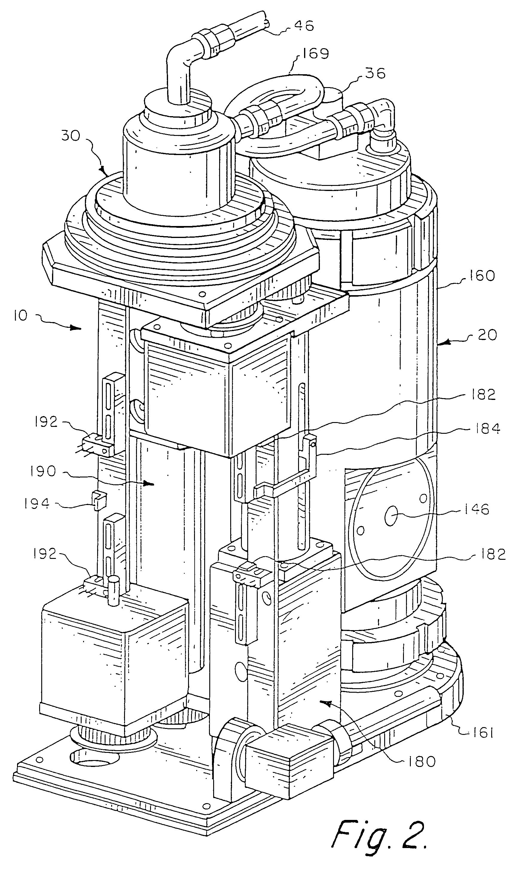
[0041]Referring now to the drawings, and particularly FIGS. 1 and 2, I show a preferred embodiment of a pump and dispense system 10 constructed in accordance with the teachings of the invention. Preferably, the system includes a first pumping means or master pump 20, and a second pumping means or slave pump 30, operably connected to pump fluid from an inlet 12 to an outlet 46. As described herein, filtering means can be included between the master and slave pumps 20 and 30, or preferably within the master pump 20 (as described herein), to filter the process fluid.

[0042]General concepts regarding the components and operation of the preferred system and its pump mechanisms are disclosed in U.S. Pat. Nos. 5,167,837, 5,516,429, and 5,772,899, which are hereby incorporated herein by reference. An overview of a preferred method of operation of the present invention is illustrated in FIG. 8. Fluid taken from an initial fluid source 60 (FIG. 8) is drawn into the system 10 through the inlet ...


PUM

PropertyMeasurementUnit
Viscosityaaaaaaaaaa
sizeaaaaaaaaaa
purityaaaaaaaaaa

Abstract

A system for dispensing and filtering fluid is disclosed, in which the fluid flow path is substantially vertical from the fluid inlet through fluid dispense. Substantially all wetted surfaces are Teflon® or some similar non-contaminating fluid, for applications such as cleanroom processes. A valve and a filter chamber are incorporated into a pump head to simplify the flow path and reduce potential contamination points. Preferred methods, and chips or other microelectronic devices fabricated from the apparatus or methods, are also disclosed.

Description

CROSS-REFERENCE TO RELATED APPLICATION[0001]This application is a divisional of, and claims a benefit of priority under 35 U.S.C. 120 of the filing date of U.S. patent application Ser. No. 10 / 641,236 by inventors Gregory M. Gibson entitled “Apparatus and Methods for Pumping High Viscosity Fluids” filed on Aug. 14, 2003, now abandoned which in turn is a divisional of U.S. patent application Ser. No. 10 / 040,235 filed Oct. 26, 2001, now U.S. Pat. No. 6,635,183, which is a divisional of U.S. patent application Ser. No. 09 / 451,498 filed Nov. 30, 1999, now U.S. Pat. No. 6,325,932, the entire contents of which are hereby expressly incorporated by reference for all purposes.[0002]The present invention relates to pumps for precisely dispensing fluids and methods related thereto, as well as various products made by those pumps and methods.BACKGROUND OF THE INVENTION[0003]This invention relates to a pumping system useful in dispensing fluids, especially those that are expensive, viscous, high ...

Claims


Application Information

Patent Timeline
Patent Type & Authority Patents(United States)
IPC IPC(8): G01F11/00B67D7/58B01D35/26B01J4/02F04B13/00F04B23/06F04B43/02F04B43/06F04B43/067F04B53/14F04B53/20
CPCB01D35/26B01D37/00F04B43/02F04B43/06F04B43/067F04B53/20F05C2225/04F04D7/04
Inventor GIBSON, GREGORY M.
Owner ENTEGRIS INC
Why Eureka
Try Eureka