Air-Operated Pump

a technology of air motor and pump, which is applied in the direction of piston pump, positive displacement liquid engine, non-mechanical valve, etc., can solve the problems of inconvenient options, inability to isolate the problem component, etc., and achieve the effect of facilitating the servicing of the air valve system

Inactive Publication Date: 2008-10-02
LINCOLN INDUSTRIES CORP
View PDF21 Cites 45 Cited by
  • Summary
  • Abstract
  • Description
  • Claims
  • Application Information

AI Technical Summary

Benefits of technology

[0004]In one embodiment, this invention is directed to an air-operated pump for pumping material, particularly a lubricant such as oil or grease. The pump comprises a head defining a cylinder, a piston reciprocal up and down in the cylinder, and a pump plunger having an upper end connected to the piston and a lower end. An elongate pump tube is connected to the head and surrounds the plunger. The pump tube extends down below the lower end of the plunger. An air motor module supplies air under pressure to the head for reciprocating the piston in the cylinder to move the pump plunger up and down in the pump tube through pumping strokes. The air motor module comprises a housing at one side of the head and an air valve system in the housing for supplying air under pressure to the head for reciprocating the piston in the cylinder. The air valve system comprises air signal valves, a relay valve and a power valve. A fastening system is provided for securing the housing to the head such that the housing may be removed as a unit from the head (e.g., to facilitate servicing of the air valve system).

Problems solved by technology

Isolation of the problem component may not be possible or practical in the field (i.e., the site where the pump is in operation).
These options are inconvenient.

Method used


Image

  • Air-Operated Pump
  • Air-Operated Pump
  • Air-Operated Pump

Examples


Embodiment Construction

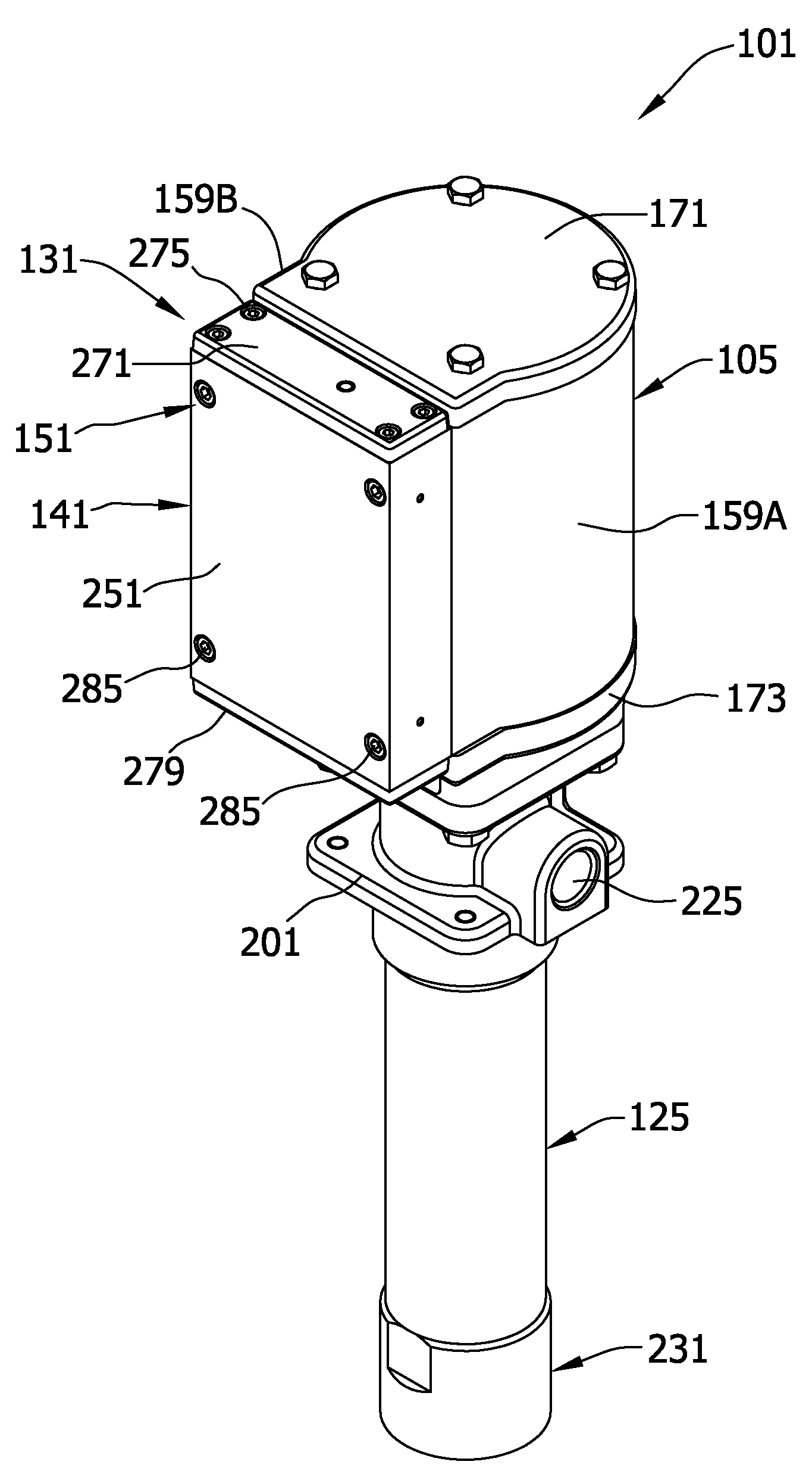
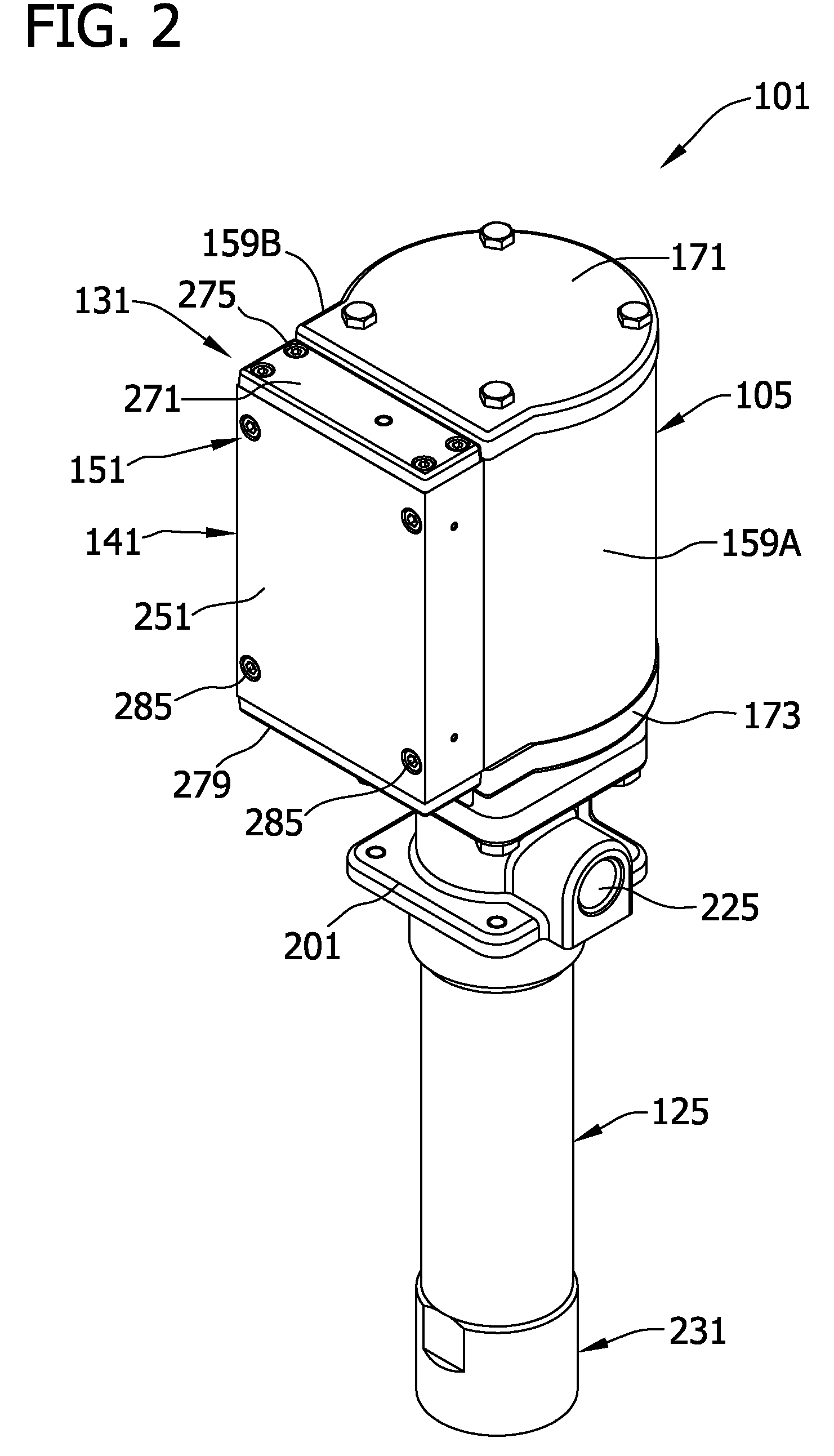
[0024]FIGS. 2-15 illustrate one embodiment of an air-operated pump of this invention, designated in its entirety by the reference number 101. The pump is operable for pumping material, particularly a lubricant such as oil or grease, from a source of such material such as a container (not shown). The pump 101 of this particular embodiment is particularly adapted for pumping oil.

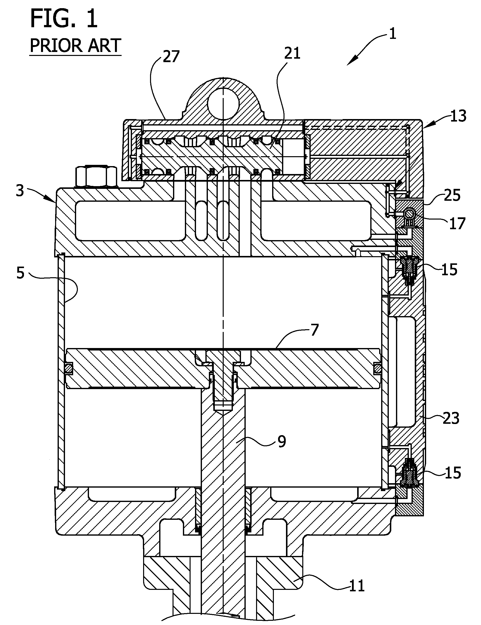
[0025]In general, and referring to FIGS. 1-7 the pump comprises a pump head 105 defining a cylinder 107 and a piston 111 reciprocal up and down in the cylinder. The cylinder 107 is divided into a first expansible chamber 115 at one side of the piston (the upper side as shown in FIG. 5) and a second expansible chamber 117 at the opposite side of the piston (the lower side as shown in FIG. 6). A pump plunger 121 extends down from the piston 111 generally co-axial with the cylinder 107. The plunger 121 has an upper end connected to the piston 111 and a lower end. An elongate pump tube 125 is connected to the head...


PUM


Abstract

An air-operated pump for pumping material such as oil or grease. The pump is powered by an air motor which operates to reciprocate a piston and plunger to effect a pumping action. The air motor is modular in that the air valve system is contained in a single housing fastened to the pump head. The housing is removable as a unit from the pump head to facilitate servicing of the air valve system.

Description

BACKGROUND OF THE INVENTION[0001]This invention relates generally to lubrication equipment, and more particularly to pumps operated by air motors for pumping lubricant such as oil or grease.[0002]FIG. 1 shows a conventional pump 1 operated by an air motor. The pump includes a head 3 comprising a cylinder 5, a piston 7 reciprocal up and down in the cylinder, and a plunger 9 connected at its upper end to the piston and extending down from the piston generally co-axially with respect to the cylinder. A pump tube 11 is connected to the head and surrounds the plunger. An air motor 13 supplies air under pressure to the head for reciprocating the piston in the cylinder to move the pump plunger up and down in the pump tube through pumping strokes, as will be understood by those skilled in this field. In general, the air motor includes an air valve system comprising a pair of air signal valves 15, a relay valve or amplifier 17 and a power valve 21, all of which are enclosed in respective hou...

Claims


Application Information

Patent Timeline
Patent Type & Authority Applications(United States)
IPC IPC(8): F04B9/125
CPCF01L25/063F04B9/1256F16N13/02F16N13/16F01L25/06F04B9/125
Inventor ARENS, THOMAS M.
Owner LINCOLN INDUSTRIES CORP
Why Eureka
Try Eureka