
Attack tool

a technology of attack tools and tools, applied in the field of attack tools, can solve problems such as wear and tear of attack tools

Active Publication Date: 2008-06-10
SCHLUMBERGER TECH CORP
View PDF133 Cites 79 Cited by
  • Summary
  • Abstract
  • Description
  • Claims
  • Application Information

AI Technical Summary

Benefits of technology

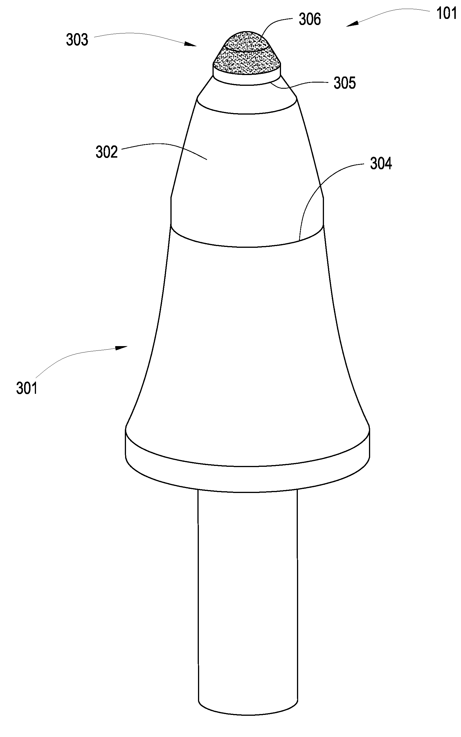
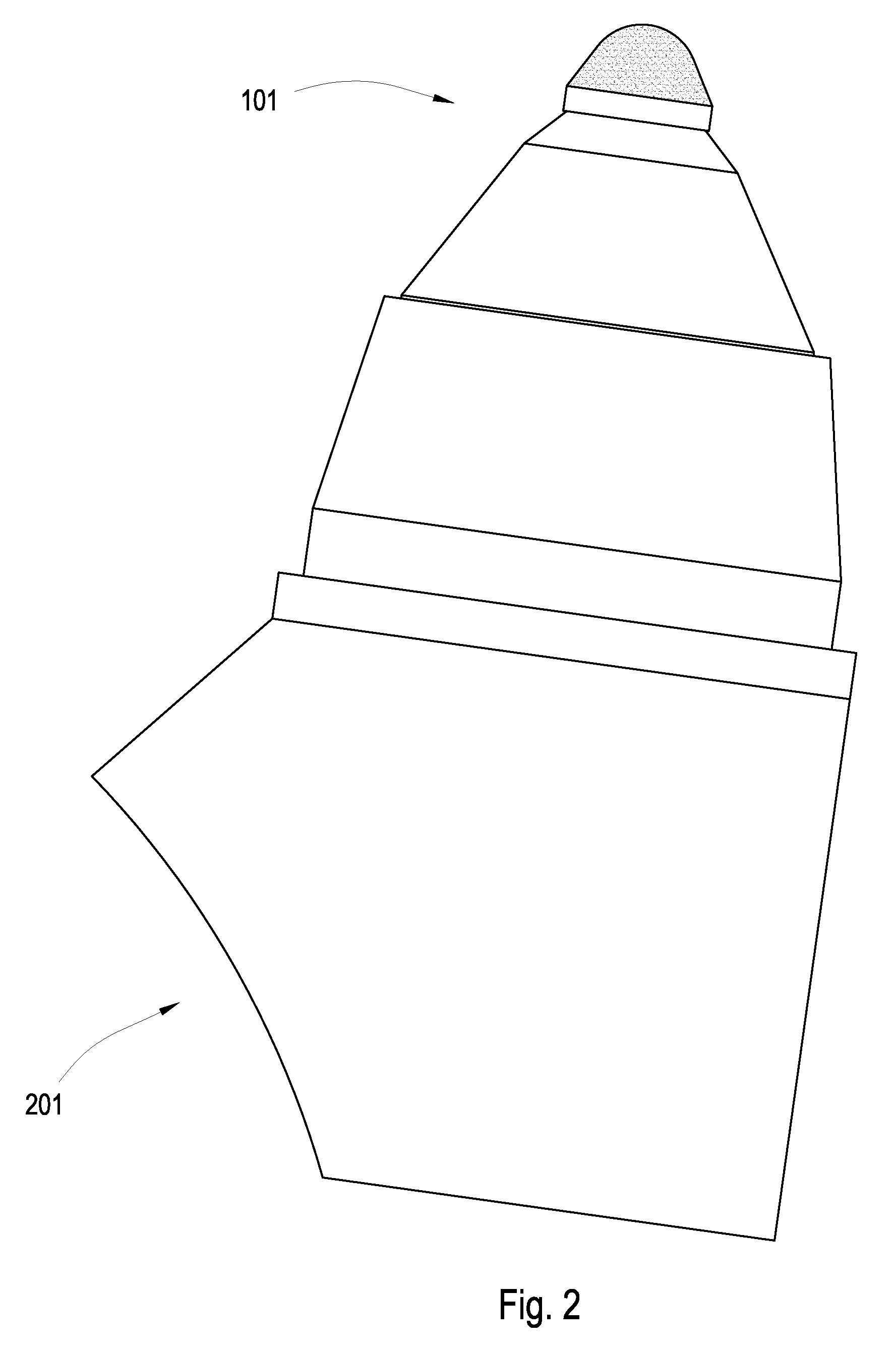
The invention is an attack tool that has a durable base and is designed to be attached to a driving mechanism. It consists of two segments of metal carbide that are bonded together. The first segment has a specific shape and size, and the second segment is attached to the first segment at a specific interface. The tool is made using a special process that ensures its strength and durability. The technical effect of this invention is to provide an improved attack tool that can withstand high levels of wear and tear during use.

Problems solved by technology

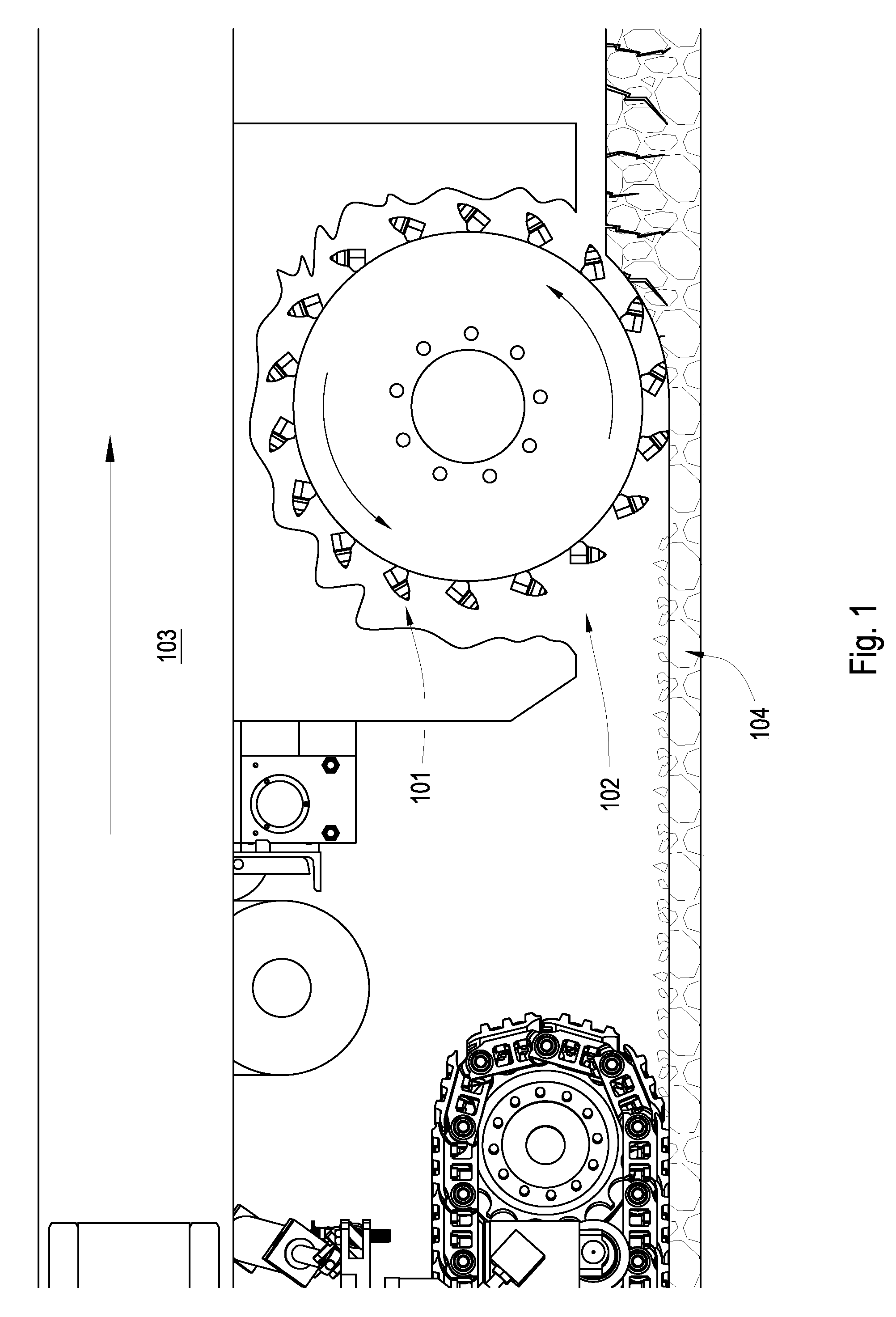
Formation degradation, such as asphalt milling, mining, or excavating, may result in wear on attack tools.

Method used


Image

  • Attack tool
  • Attack tool
  • Attack tool

Examples


Embodiment Construction

[0040]It will be readily understood that the components of the present invention, as generally described and illustrated in the Figures herein, may be arranged and designed in a wide variety of different configurations. Thus, the following more detailed description of embodiments of the methods of the present invention, as represented in the Figures is not intended to limit the scope of the invention, as claimed, but is merely representative of various selected embodiments of the invention.

[0041]The illustrated embodiments of the invention will best be understood by reference to the drawings, wherein like parts are designated by like numerals throughout. Those of ordinary skill in the art will, of course, appreciate that various modifications to the methods described herein may easily be made without departing from the essential characteristics of the invention, as described in connection with the Figures. Thus, the following description of the Figures is intended only by way of exa...


PUM

PropertyMeasurementUnit
weight percentaaaaaaaaaa
volumeaaaaaaaaaa
melting temperatureaaaaaaaaaa

Abstract

In one aspect of the invention, an attack tool is disclosed which has a wear-resistant base suitable for attachment to a driving mechanism, a first cemented metal carbide segment brazed to the base at a first interface, and a second metal carbide segment brazed to the first carbide segment at a second interface opposite the base. The attack tool also having a braze material disposed in the second interface with 30 to 62 weight percent of palladium.

Description

CROSS REFERENCE IS RELATED APPLICATIONS[0001]This application is a continuation-in-part of U.S. patent application Ser. No. 11 / 463,990 which was filed on Aug. 11, 2006 now U.S. Pat. No. 7,320,505 and entitled An Attack Tool. U.S. patent application Ser. No. 11 / 463,990 is a continuation-in-part of U.S. patent application Ser. No. 11 / 463,975 which was filed on Aug. 11, 2006 and entitled An Attack Tool. U.S. patent application Ser. No. 11 / 463,975 is a continuation in-part of U.S. patent application Ser. No. 11 / 463,962 which was filed on Aug. 11, 2006 and entitled An Attack Tool. All of these applications are herein incorporated by reference for all that it contains.BACKGROUND OF THE INVENTION[0002]Formation degradation, such as asphalt milling, mining, or excavating, may result in wear on attack tools. Consequently, many efforts have been made to extend the life of these tools. Examples of such efforts are disclosed in U.S. Pat. No. 4,944,559 to Sionnet et al., U.S. Pat. No. 5,837,071 ...

Claims


Application Information

Patent Timeline
Patent Type & Authority Patents(United States)
IPC IPC(8): E21C25/10E21C35/19
CPCE21C35/183E21C35/19E21C35/197E21C2035/1806E21C35/1831
Inventor HALLCROCKETT, RONALDJEPSON, JEFF
Owner SCHLUMBERGER TECH CORP
Learn More