Printhead IC with nozzle array for linking with adjacent printhead IC's

a technology of printheads and nozzle arrays, applied in the field of inkjet printers, can solve the problems of nozzle burnout of entire printheads, inability to control the operation of arrays of nozzles in one printhead, and inability to replace entire printheads, so as to prevent nozzle burnout and reduce the duration of drive pulses

Active Publication Date: 2008-06-10
MEMJET TECH LTD +1
View PDF9 Cites 82 Cited by
  • Summary
  • Abstract
  • Description
  • Claims
  • Application Information

AI Technical Summary

Benefits of technology

[0012]Inclining a section of the nozzle rows down to meet the drop triangle, avoids sharp corners in the corresponding supply conduit.
[0112]Making the printhead IC's compatible with different data transmission protocols increases the versatility of the printhead IC design. A versatile design lowers the types of chip that need to be fabricated thereby lowering production costs.Optionally, one of the data transmission protocols is a self clocking data signal and another data transmission protocol has separate clock and data signals.Optionally, connection to a power source within the printer, the drive circuitry cycles through different operating modes until it aligns with the data transmission protocol being used by the PEC.Optionally, the drive circuitry is configured to extract a clock signal from the data transmission from the PEC.Optionally, the data transmission is a digital signal that has a rising edge at every clock period.Optionally, the drive circuitry determines a data bit from every clock period by the position of the falling edge during that period.

Problems solved by technology

This allows much higher print speeds but is more complicated in terms of controlling the operation of a much larger array of nozzles.
Furthermore, localized fabrication defects can render an entire printhead IC defective.
Unfortunately, the array of nozzles in one printhead IC can not simply abut the array of nozzles on an adjacent printhead IC.
The sides of the printhead IC's can not be manufactured accurately enough to position the end nozzles of one IC close enough to the nozzles of the next IC without visible artifacts in the printed image.

Method used


Image

  • Printhead IC with nozzle array for linking with adjacent printhead IC's
  • Printhead IC with nozzle array for linking with adjacent printhead IC's
  • Printhead IC with nozzle array for linking with adjacent printhead IC's

Examples


Embodiment Construction

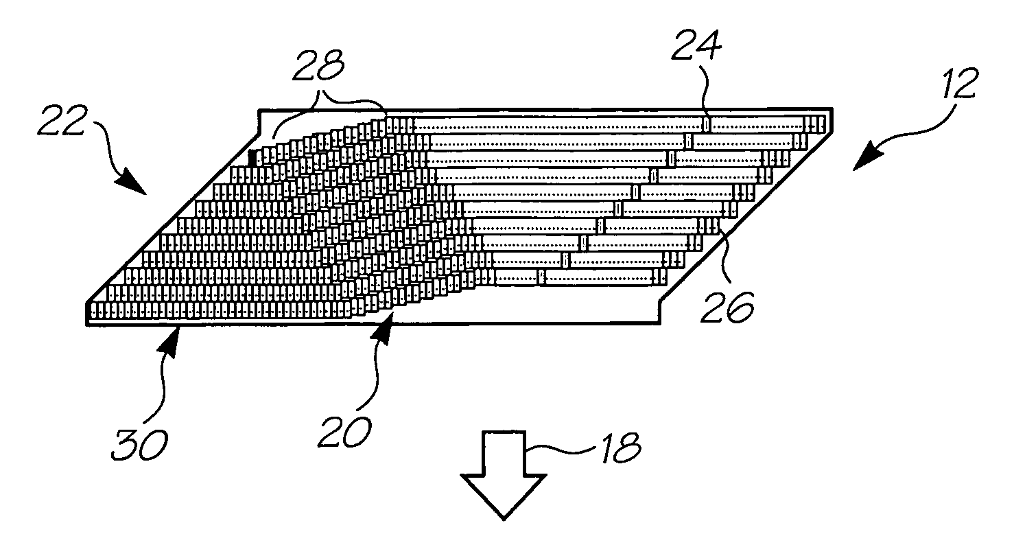
[0148]The Applicant has developed a range of printhead devices that use a series of printhead integrated circuits (ICs) that link together to form a pagewidth printhead. In this way, the printhead IC's can be assembled into printheads used in applications ranging from wide format printing to cameras and cellphones with inbuilt printers. One of the more recent printhead IC's developed by the Applicant is referred to internally as wide range of printing applications. The Applicant refers to these printhead IC's as ‘Udon’ and the various aspects of the invention will be described with particular reference to these printhead IC's. However, it will be appreciated that this is purely for the purposes of illustration and in no way limiting to the scope and application of the invention.

Overview

[0149]The Udon printhead IC is designed to work with other Udon ICs to make a linking printhead. The Applicant has developed a range of linking printheads in which a series of the printhead IC's are m...


PUM


Abstract

A printhead IC for an inkjet printer that mounts the printhead IC together with at least one other like printhead IC to provide a pagewidth printhead for printing onto a media substrate fed past the printhead in a feed direction, the printhead IC comprising: an elongate array of nozzles, the nozzles arranged into rows, at least one of the rows having a first section positioned on a line extending perpendicular to the feed direction, a second section positioned along a parallel line displaced from the first section, and an intermediate section of nozzles extending between the first section and the second section; and a supply conduit for providing printing fluid to the first section, the second section and the intermediate section, the supply conduit having a first portion extending perpendicular to the feed direction for supplying the first section of nozzles, a second portion extending perpendicular to the feed direction for supplying the second section of nozzles and an inclined portion for supplying the intermediate section of nozzles.

Description

FIELD OF THE INVENTION[0001]The present invention relates to the field of inkjet printers. In particular, the invention relates to inkjet printers that have printheads with a number of separate printhead integrated circuits (IC's) defining the nozzles that eject the ink or other printing fluid.CO-PENDING APPLICATIONSThe following applications have been filed by the Applicant simultaneously with the present application:[0002]PUA001USPUA002USPUA003USPUA004USPUA005USPUA006USPUA007USPUA008USPUA009USPUA011USPUA012USPUA013USPUA014USPUA015USMTE001USMTE002USThe disclosures of these co-pending applications are incorporated herein by reference. The above applications have been identified by their filing docket number, which will be substituted with the corresponding application number, once assigned.CROSS REFERENCES TO RELATED APPLICATIONSVarious methods, systems and apparatus relating to the present invention are disclosed in the following US patents / patent applications filed by the applican...

Claims


Application Information

Patent Timeline
Patent Type & Authority Patents(United States)
IPC IPC(8): B41J2/155
CPCB41J2/0451B41J2/04541B41J2/04551B41J2/04563B41J2/04573B41J2/0458B41J2/04588B41J2/04591B41J2/04596B41J2002/14403B41J2202/20
Inventor SHEAHAN, JOHN ROBERTPULVER, MARK JACKSONFOOTE, ROGER MERVYN LLOYDMORAHAN, BRIAN CHRISTOPHERMOINI, ALIREZAGILLESPIE, TIMOTHY PETERWEBB, MICHAEL JOHNSILVERBROOK, KIA
Owner MEMJET TECH LTD
Why Eureka
Try Eureka