Connector, connector assembly and assembling method

a connector and assembly technology, applied in the direction of coupling device connection, coupling parts engagement/disengagement, incorrect coupling prevention, etc., can solve the problem of difficult to constantly define the clearance for each product in view of variation in production, difficult to move the jaw above the step, and difficulty in starting the lever rotation, etc. problem, to achieve the effect of preventing loose movement and improving the operation of the movable member for connecting the housing with the mating housing

Active Publication Date: 2008-06-10
SUMITOMO WIRING SYST LTD
View PDF30 Cites 15 Cited by
  • Summary
  • Abstract
  • Description
  • Claims
  • Application Information

AI Technical Summary

Benefits of technology

[0007]The invention relates to a connector with a housing connectable with a mating housing. A movable member having at least one cam groove is mounted movably to the housing and is engageable with at least one cam pin projecting in the mating housing. A stepped or recessed surface is engageable with a jaw of the cam pin and is formed at an intermediate position of the cam groove with respect to a depth direction. The depth of the step of the cam groove in the operable member is larger at the entrance side of the cam groove so that the jaw can be accommodated loosely into an accommodating portion of the cam groove. However, the depth decreases towards the back side of the cam groove so that the jaw can be accommodated in the accommodating portion while having loose movements prevented. Accordingly, the operation of the movable member for connecting the housing with a mating housing is improved.

Problems solved by technology

If this clearance is too small, it may be difficult for the jaw to move above the step.
Thus, a contact pressure of the step of the cam groove and the jaw becomes too high, which might result in difficulty in starting the lever rotation.
In short, there is no problem if the clearance is set suitably, but it is difficult to constantly define a specified clearance for each product in view of variation in production.

Method used


Image

  • Connector, connector assembly and assembling method
  • Connector, connector assembly and assembling method
  • Connector, connector assembly and assembling method

Examples


Embodiment Construction

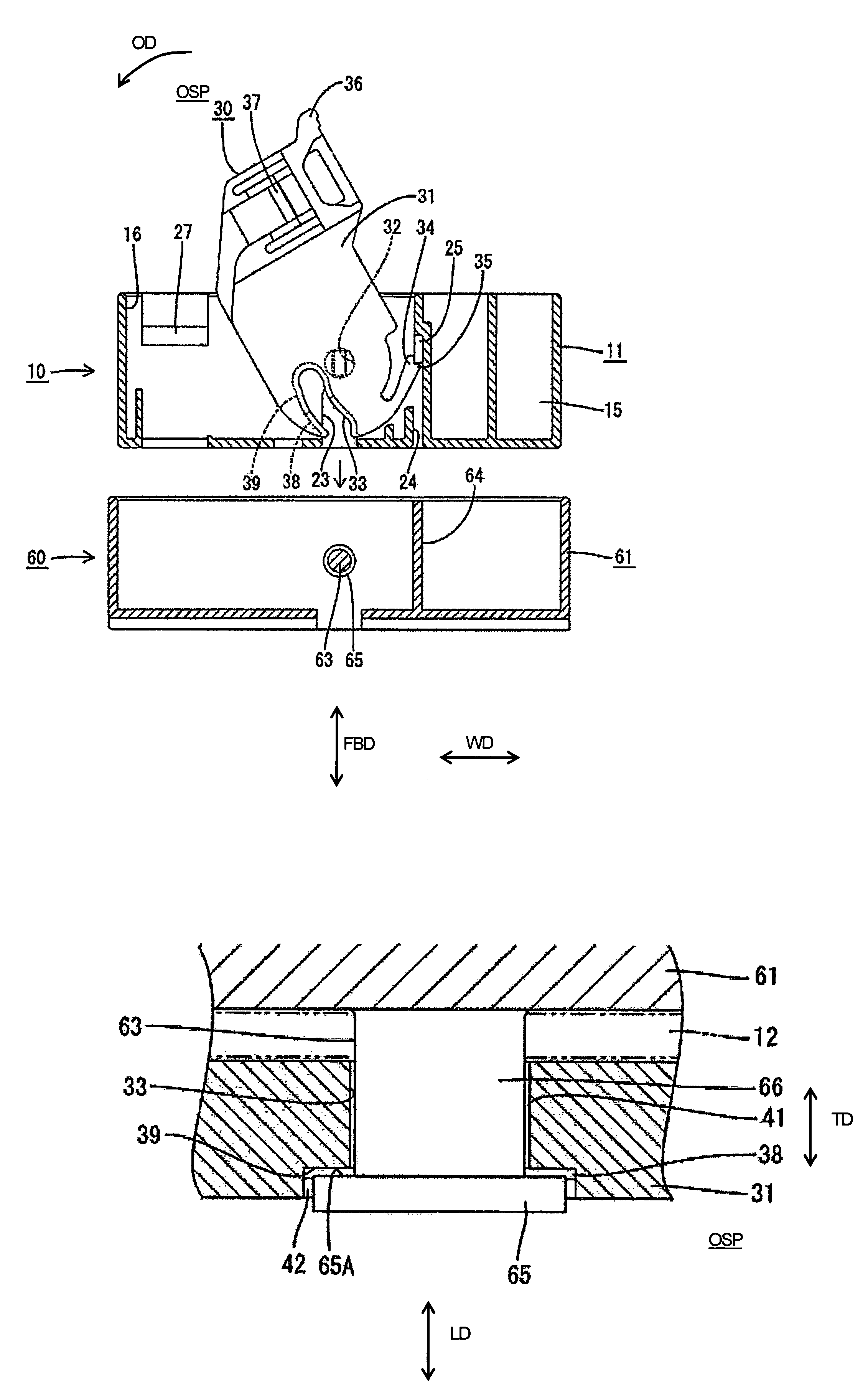
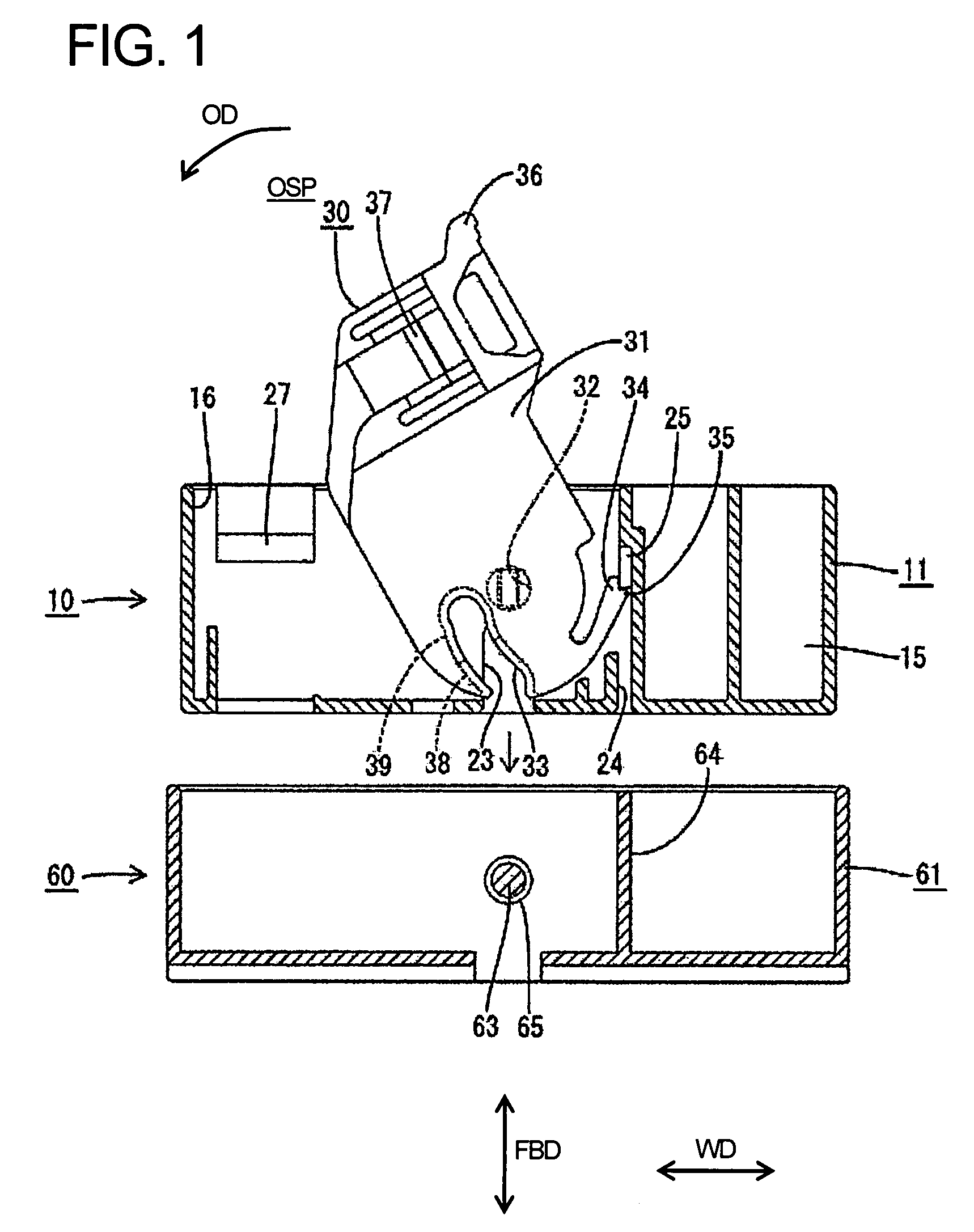
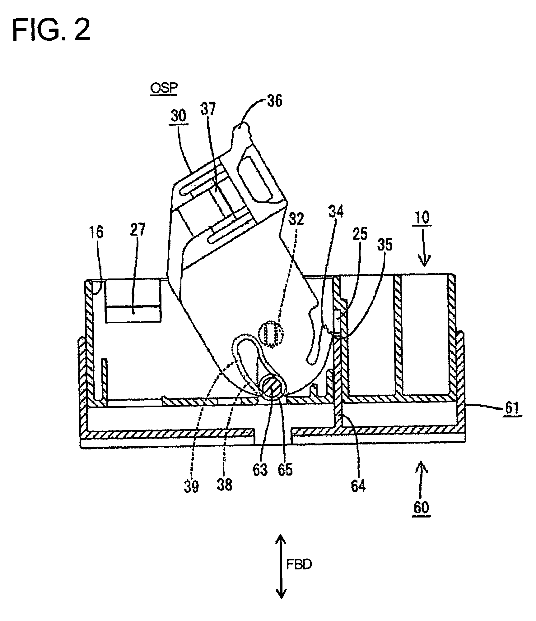
[0024]A connector assembly according to the invention is illustrated in FIGS. 1 to 9. The connector assembly has female and male housings 10, 60 that connectable with and separable from each other as shown in FIG. 1. In the following description, ends of the two housings 10, 60 to be connected are referred to as the fronts concerning forward and backward directions FBD and reference is made to FIG. 4 concerning vertical direction.

[0025]The female housing 10 includes a holder 11 in the form of a wide rectangular frame capable of accommodating auxiliary housings (not shown). A lever 30 is assembled into the holder 11.

[0026]The holder 11 is made e.g. of synthetic resin and has an upper wall 12, a bottom wall 13 and left and right side walls 14, as shown in FIG. 7. A ceiling wall 15 is disposed below the upper wall 12, and a wide lever accommodating portion 16 is defined between the ceiling wall 15 and the upper wall 12 for accommodating the lever 30. Two partition plates 17 extend betw...


PUM


Abstract

A connector has female and male housings (10, 60). A cam pin (63) projects from the male housing (60), and a jaw (65) bulges out at the end of the cam pin (63). A lever (30) is mounted to the female housing (10), and has a cam groove (33) for engaging the cam pin (63). A step (38, 39) in the cam groove (33) defines an accommodating portion (42) for the jaw (65). The depth of the accommodation portion (42) is larger near the entrance of the cam groove (33) so that the jaw (65) initially is accommodated loosely. However the depth of the accommodating portion (42) is smaller towards the back of the cam groove (33) to prevent loose movements.

Description

BACKGROUND OF THE INVENTION[0001]1. Field of the Invention[0002]The invention relates to a lever-type connector, to a connector assembly and to an assembling method therefor.[0003]2. Description of the Related Art[0004]Japanese Unexamined Patent Publication No. 2004-14142 discloses a lever-type connector with first and second housings that are connectable with each other. A lever formed with a cam groove is mounted in first housing and the second housing includes a cam pin. A jaw bulges radially out at the leading end of the cam pin and engages a step at an intermediate position of the cam groove. The step extends substantially horizontally at the same depth along the cam groove, and a space above the step accommodates the jaw. The cam pin enters the cam groove when the two housings are fit lightly together. The lever then is rotated so that the cam pin moves towards the back of the cam groove to urge the housings to a properly connected state. The jaw slides on the step so that the...

Claims


Application Information

Patent Timeline
Patent Type & Authority Patents(United States)
IPC IPC(8): H01R13/62
CPCH01R13/62938H01R13/6295H01R13/62955H01R13/631
Inventor IMAI, YUUJIROUSHINOZAKI, TETSUYA
Owner SUMITOMO WIRING SYST LTD
Why Eureka
Try Eureka