Coaxial cable end connector

a technology of end connector and coaxial cable, which is applied in the direction of coupling device connection, coupling device details, contact members penetrating/cutting insulation/cable strands, etc., can solve the problems of inconvenient carrying a lot of tools, additional costs and tools, etc., and achieves effective and tightly connected

Active Publication Date: 2008-06-10
EZCONN
View PDF13 Cites 31 Cited by
  • Summary
  • Abstract
  • Description
  • Claims
  • Application Information

AI Technical Summary

Benefits of technology

[0006]A primary object of the present invention is to provide a coaxial cable end connector that is connected to a coaxial cable via a clamping structure. The clamping structure includes at least one sliding member mounted in a transverse slot provided on an outer sleeve of the end connector and having a plurality of teeth provided on a bottom surface thereof, such that the sliding member can be forced toward a center of the outer sleeve to tightly press the teeth against the jacket of a coaxial cable inserted into the end connector, causing the end connector to effectively and tightly connected to an end of the coaxial cable.

Problems solved by technology

Therefore, additional costs and tools are needed to complete the connection of the conventional coaxial cable connector to the coaxial cable, and it is inconvenient for an operator to carry a lot of tools for the purpose of connecting the connector to the coaxial cable.

Method used


Image

  • Coaxial cable end connector
  • Coaxial cable end connector
  • Coaxial cable end connector

Examples


Embodiment Construction

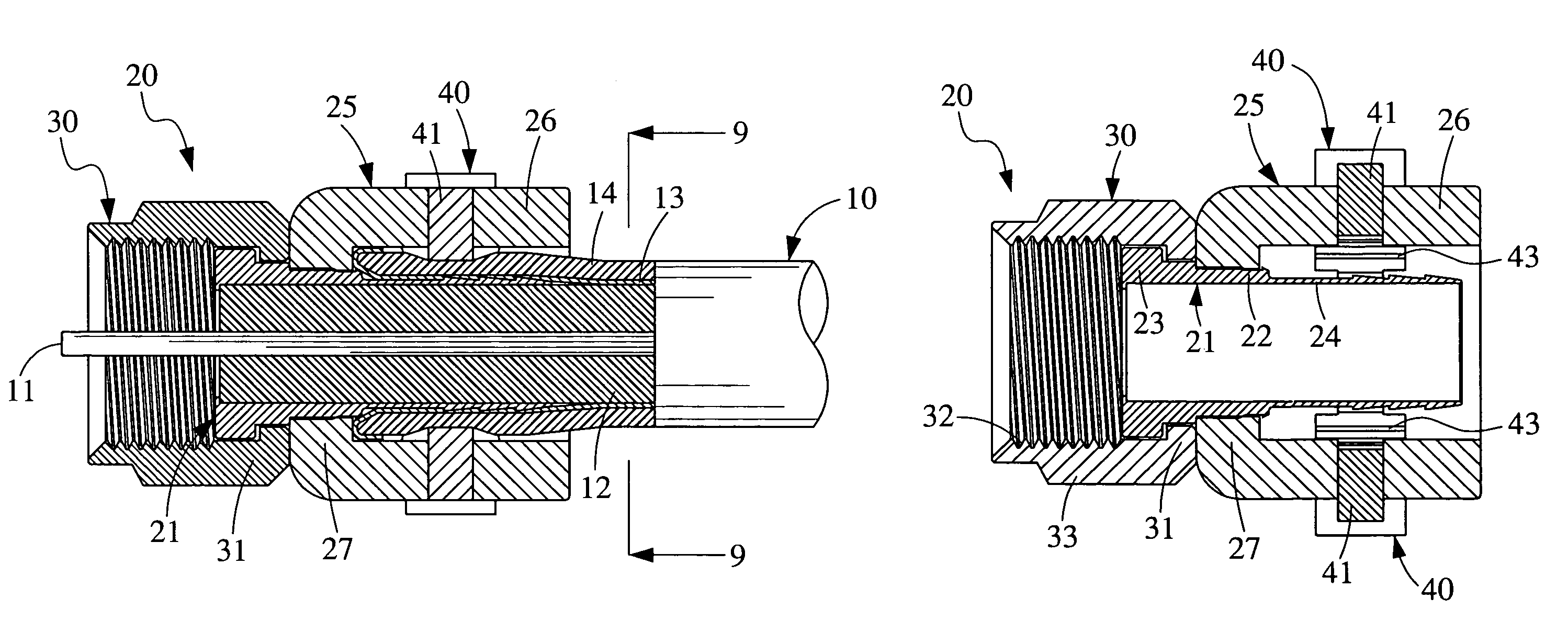
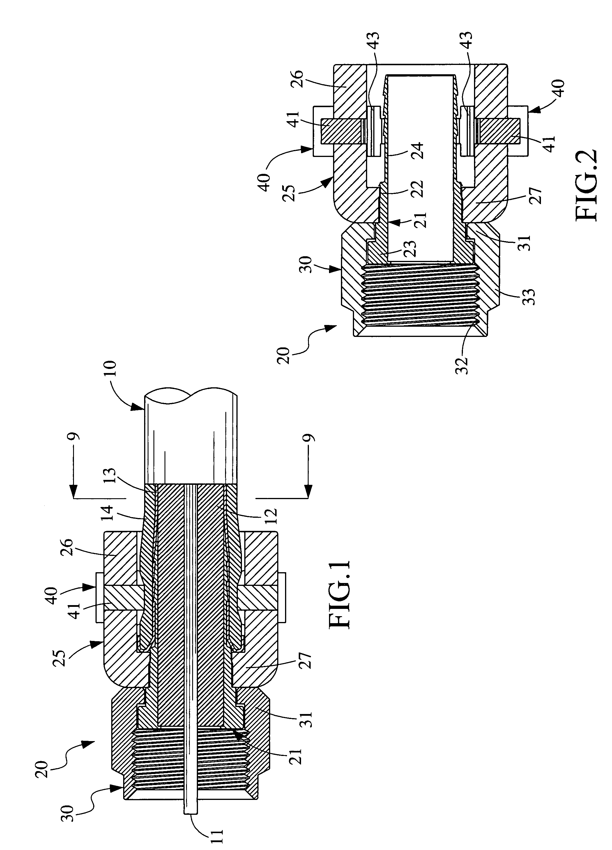
[0017]Please refer to FIG. 1. A conventional coaxial cable 10 consists of a central conductor 11, an insulator 12 surrounding the central conductor 11, at least one layer of braided conducting sheath 13 surrounding the insulator 12, and a jacket 14 surrounding the braided conducting sheath 13. To ensure effective connection of the coaxial cable 10 to a receiver and terminal, for example, a front end of the coaxial cable 10 must be stripped by a predetermined distance, and the exposed braided conducting sheath 13 thereat must be separated from the insulator 12 and then turned backward to overlap the jacket 14, so as to expose the central conductor 11 and the insulator 12 at the front end of the coaxial cable 10.

[0018]As can be seen from FIGS. 1 and 2, a coaxial cable end connector 20 according to the present invention includes an inner sleeve 21 and an outer sleeve 25.

[0019]The inner sleeve 21 has a front portion formed into a radially outward extended flange 23, a rear portion forme...


PUM


Abstract

A coaxial cable end connector includes two hollow and coaxial inner and outer sleeves. The outer sleeve is provided with at least one transverse slot for receiving a clamping structure therein. The clamping structure is formed at a bottom surface with a plurality of teeth. When a coaxial cable is inserted into the end connector, the jacket and the braided conducting sheath of the cable are located in an annular space between the inner and the outer sleeve. By forcing the clamping structure toward a center of the outer sleeve, the teeth at the bottom surface of the clamping structure are brought to tightly press against and connect to the jacket of the coaxial cable.

Description

FIELD OF THE INVENTION[0001]The present invention relates to a coaxial cable end connector for connecting a coaxial cable to a specified device, such as a dedicated receiver or terminal on a cabled TV; and more particularly to a coaxial cable end connector that is connected to a coaxial cable via a clamping structure.BACKGROUND OF THE INVENTION[0002]A coaxial cable connector is a widely known device. Many coaxial cable connector types are available in the market. Among others, a type F connector is typically screwed to a complementary interface connector for electrically connecting a coaxial cable to different types of electronic devices, such as TV sets, CB (citizens' band) radios, FM (frequency modulation) radios, and other amateur radio systems.[0003]A conventional coaxial cable connector includes a main body having a ring member, a cylindrical member coaxially arranged in the ring member, and a nut fitted around the cylindrical member.[0004]The coaxial cable connector is connect...

Claims


Application Information

Patent Timeline
Patent Type & Authority Patents(United States)
IPC IPC(8): H01R9/05
CPCH01R9/0524H01R13/5812
Inventor WANG, CHAO-PIN
Owner EZCONN
Why Eureka
Try Eureka