Control system and lighting control system

a control system and intelligent technology, applied in the direction of digital computer details, instruments, nuclear elements, etc., can solve the problems of difficult to solve the problem of adjusting a plurality of control targets, trial and error, and adjustment necessary

Inactive Publication Date: 2008-06-10
DOSHISHA THE
View PDF4 Cites 16 Cited by
  • Summary
  • Abstract
  • Description
  • Claims
  • Application Information

AI Technical Summary

Benefits of technology

[0006]An object of the present invention is to provide a lighting control system capable of setting the illumination of a predetermined position to a desired illumination and reducing the energy consumption, using a plurality of lighting devices in places such as in a hall, in an ordinary room, and outdoors. Furthermore, it is an object to provide a control system that is compatible not only with lighting control, but also with similar control issues.
[0033]With the above-described control systems, it is possible to control an observation amount in a predetermined position, such as an illumination, to a desired value. Furthermore, it is possible to control the amount to a condition in which energy consumption is low.

Problems solved by technology

However, with the systems in the above-described conventional technology, in order to set a desired illumination in desired locations in audience seats and on stage for example, trial and error and adjustments have been necessary as with conventional systems.
On the other hand, although commonly known automatic control may be used to adjust a single point of illumination of a single light source to a predetermined target value, in cases such as where a plurality of light sources are used and the overall illumination distribution in a room is to be set to a desired condition, it has not been easy to solve the issues of adjusting a plurality of control targets to set and maintain a condition in which a plurality of target values are met.

Method used


Image

  • Control system and lighting control system
  • Control system and lighting control system
  • Control system and lighting control system

Examples


embodiment 1

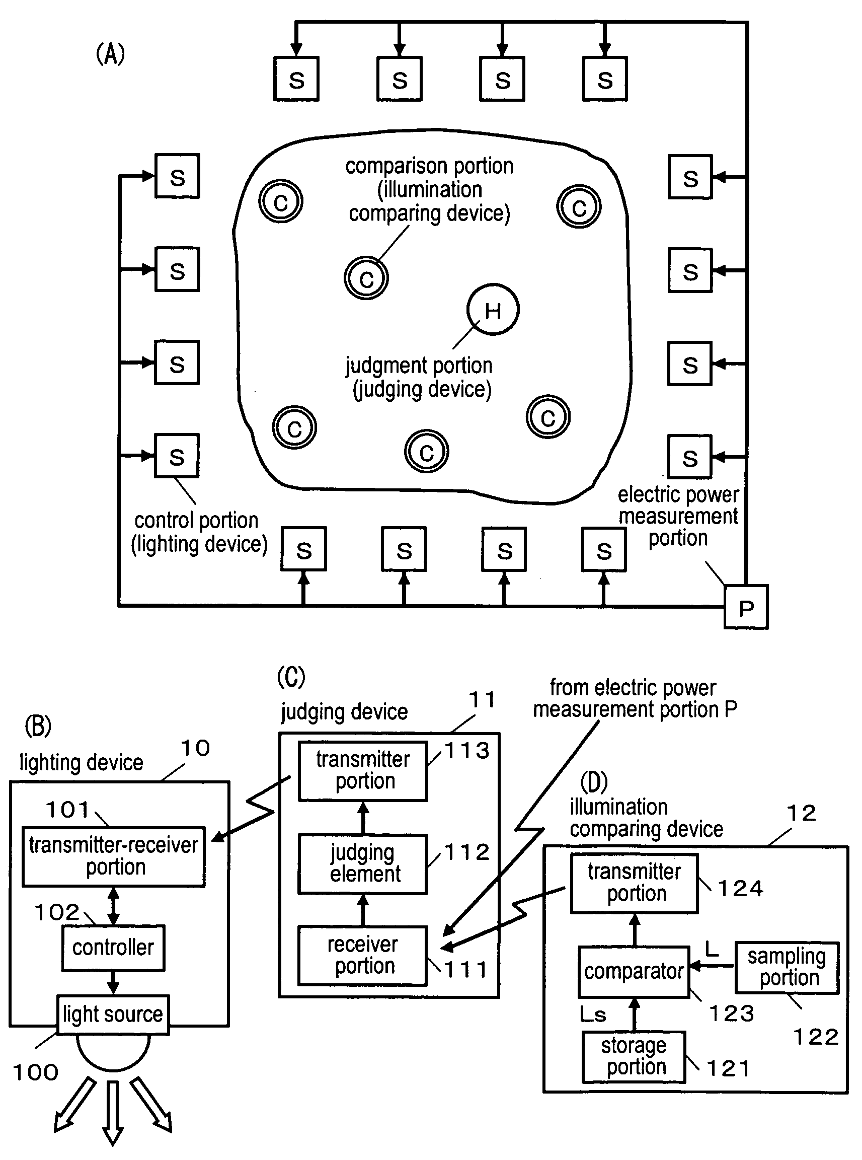
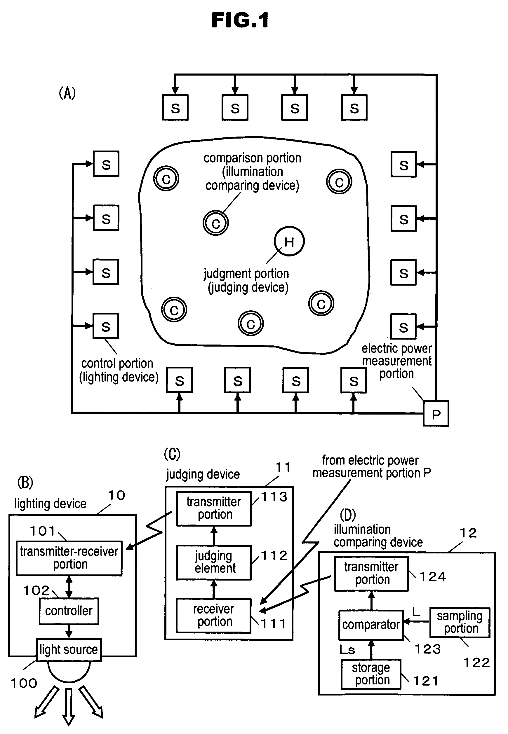
[0045]FIG. 1 is a diagram showing a control system according to the present invention. In FIG. 1, a plurality of control portions S, at least one comparison portion C and at least one judgment portion H are provided. An electric power measurement portion P is also provided. The electric power measurement portion P measures the amount of electric power supplied to the control portions S, and sends to the judgment portion H electric power information expressing the amount of electric power or the increase / decrease of electric power. The comparison portion C is provided with a sampling portion that samples observation information and a storage portion that has target information, and sends to the judgment portion H a comparison result in which the observation information and the target information are compared. The judgment portion H carries out a predetermined judgment, i.e., a judgment as to whether a predetermined condition is met, based on the electric power information and the com...

embodiment 2

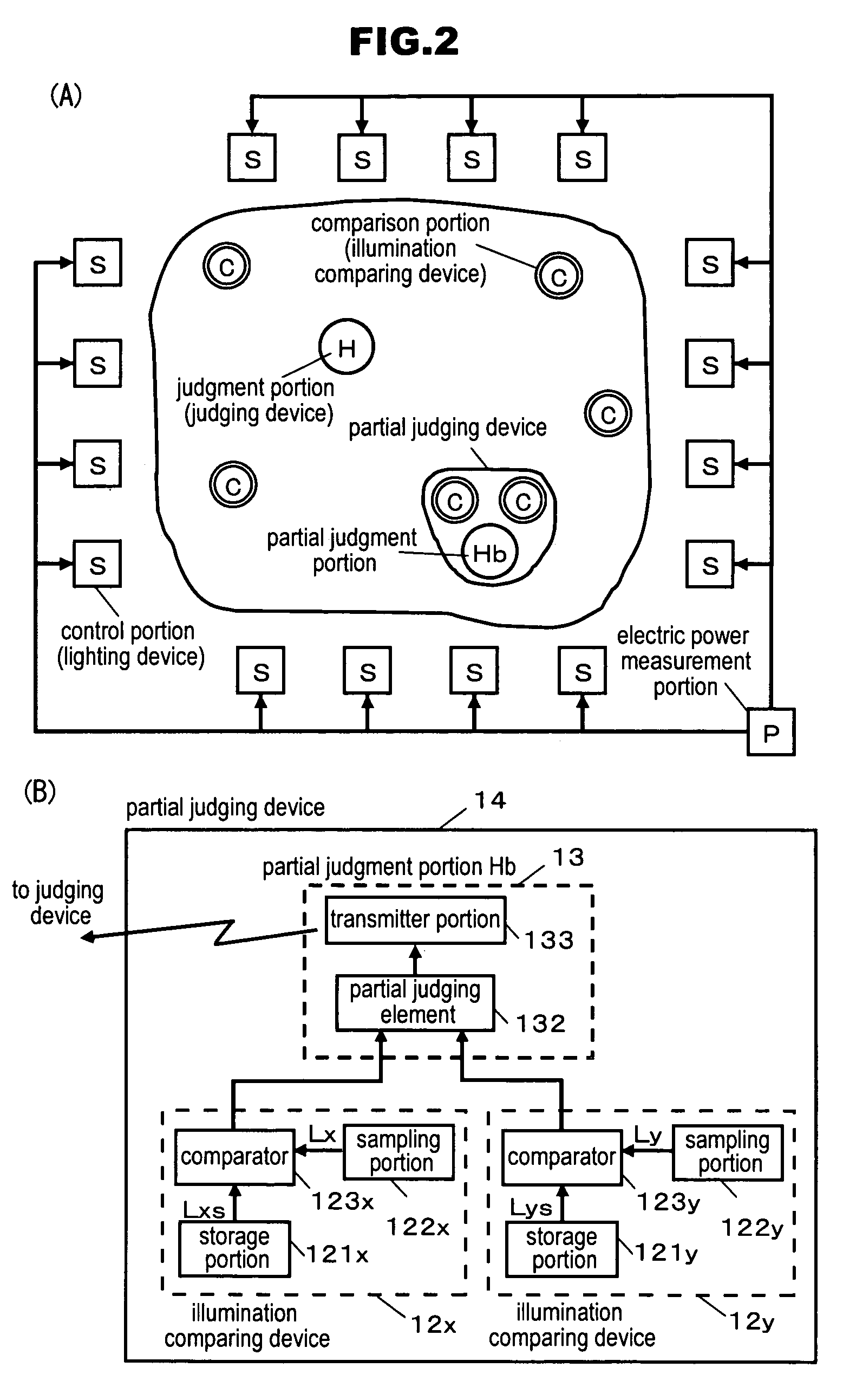
[0067]FIG. 2(A) is a diagram of another embodiment of the present invention, wherein a partial judgment portion Hb is introduced. In FIG. 2(A), two comparison portions C and the partial judgment portion Hb constitute a partial judging device. FIG. 2(B) is a block diagram showing a configuration of a partial judging device 14. An illumination comparing device 12x is provided with a storage portion 121x, a sampling portion 122x and a comparator 123x, and sends a comparison result between a target illumination Lxs and a sampled illumination Lx to a partial judging element 132 of a partial judgment portion 13. An illumination comparing device 12y is provided with a storage portion 121y, a sampling portion 122y and a comparator 123y, and sends a comparison result between a target illumination Lys and a sampled illumination Ly to the partial judging element 132. The partial judging element 132 carries out the above-described predetermined judgment for the comparison results from the two i...

embodiment 3

[0072]FIG. 3(A) shows an example in which the judgment portion H is provided to each of the control portions S, which are lighting devices. FIG. 3(B) shows a lighting device 15 that includes a judging element 112, which is an equivalent of the judgment portion H. The lighting device 15 receives the comparison results, the partial judgment result and the electric power information from the transmitter-receiver portion 101, and carries out the predetermined judgment in the judging element 112. In accordance with the judgment result, the controller 102 carries out variation control or return control. The procedure of the flowchart described with reference to FIG. 4 can also be applied in this embodiment.


PUM


Abstract

The invention judges whether or not the relation between an illumination at a desired position and a target illumination satisfies a predetermined condition, and causes the illumination at the desired position to approach the target illumination by letting a plurality of lighting devices successively perform a procedure of increasing / decreasing their respective light intensities based on a result of the judgment. The illumination at the desired position is caused to approach the target illumination by randomly varying the light intensities of the lighting devices, making comparison between the illumination at the desired position and the target illumination, and narrowing the width of variation based on a result of the comparison. When the electric power consumption has increased, the light intensities are returned to the previous values. Furthermore, there is provided a control terminal device for control that can be used for other control amounts.

Description

TECHNICAL FIELD[0001]The present invention relates to an intelligent control system and an intelligent lighting control system that can be used for lighting control for example, the control systems being capable of reduction of energy consumption, as well as flexible control and management of illumination, for example.BACKGROUND ART[0002]With conventional lighting systems, when numerous light sources are provided in a hall for example, the light intensities of the light sources are adjusted individually to set the illumination appropriately for numerous locations inside the hall. With such a technique, it is necessary to repetitively adjust each of the light sources using trial and error to set the illumination at a predetermined position to a desired value. Also, it is necessary to adjust the light intensity of each of the light sources regularly or for each performance, if the illumination of the lamps changes over time. Similarly, adjustments are necessary when the illuminant has...

Claims


Application Information

Patent Timeline
Patent Type & Authority Patents(United States)
IPC IPC(8): G21C17/00G06F11/30G05D23/00H05B37/02H05B41/392
CPCH05B37/02H05B47/10
Inventor MIKI, MITSUNORI
Owner DOSHISHA THE
Why Eureka
Try Eureka