
Rocket exhaust defense system and method

Inactive Publication Date: 2008-06-17
THE UNITED STATES OF AMERICA AS REPRESENTED BY THE SECRETARY OF THE NAVY
View PDF29 Cites 16 Cited by
  • Summary
  • Abstract
  • Description
  • Claims
  • Application Information

AI Technical Summary

Benefits of technology

[0007]Another object of the present invention to provide a system and method for detecting the approach of an incoming and then deflecting or otherwise defeating the projectile so it does not impact the intended target.

Problems solved by technology

In a variety of world conflicts today, vehicles and structures are vulnerable to attack from inexpensive shoulder-launched projectiles / munitions such as rocket-propelled grenades (RPGs) and their variants.
Unfortunately, turning every vehicle into an improvised tank (or structure into a fortress) is not practical or cost effective.
However, this type of system can be expensive since it must possess precise target acquisition and aiming capabilities.
Furthermore, this type of system can be a threat to friendly forces and noncombatants as any missed intercepts could result in bullets entering a nearby population.
Whether passive or active in nature, initiating an RPG (even at a distance) is not necessarily the optimal defeat mechanism.

Method used


Image

  • Rocket exhaust defense system and method
  • Rocket exhaust defense system and method
  • Rocket exhaust defense system and method

Examples


Embodiment Construction

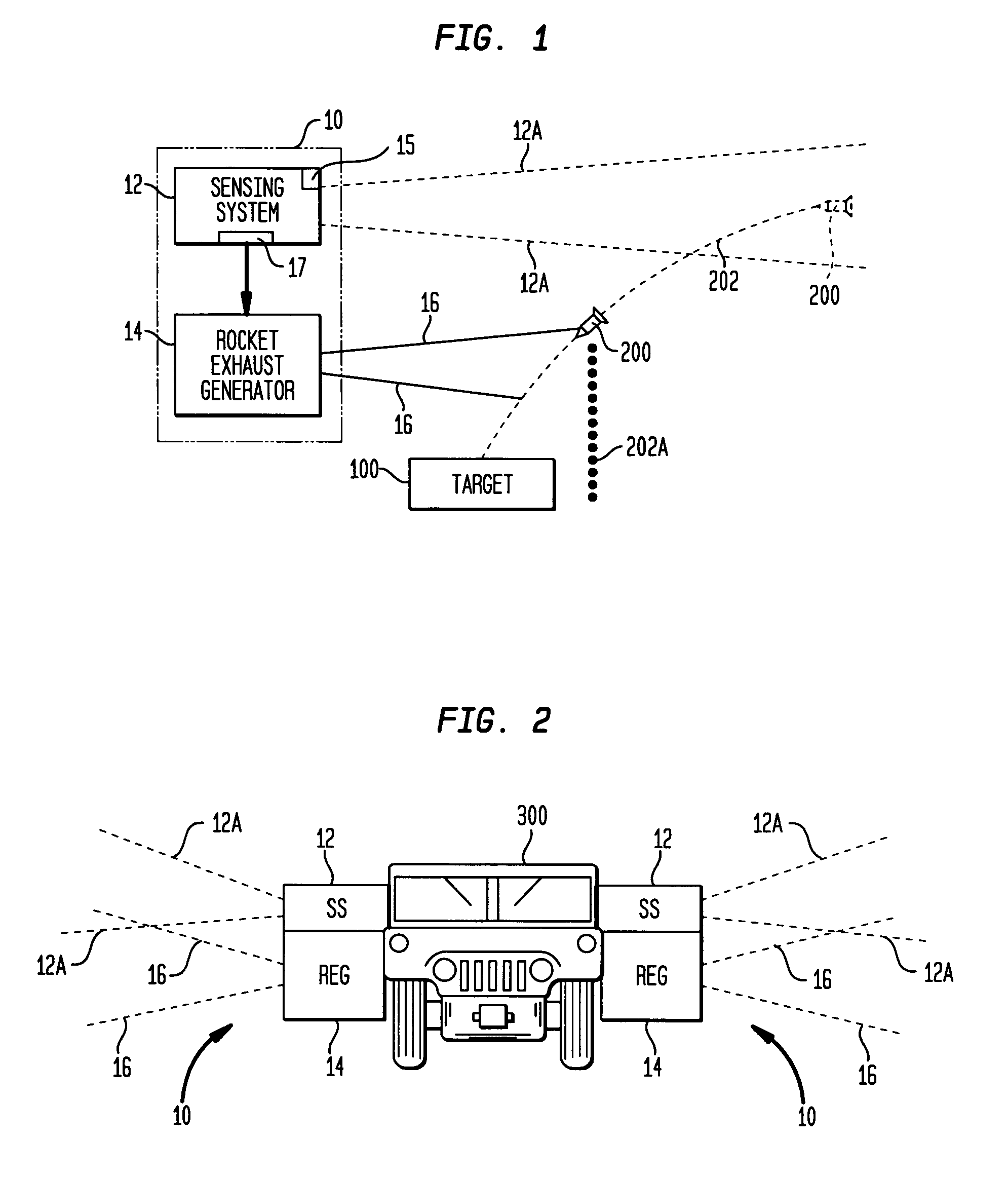
[0015]Referring now to the drawings, and more particularly to FIG. 1, a projectile defense system in accordance with the present invention is contained within a dashed line box 10. Projectile defense system 10 can be used to defend a target 100 against a variety of incoming projectile threats such as projectile 200 which, for purposes of this example, is assumed to be traveling on a trajectory 202 that will cause it to impact target 100. It is to be understood that target 100 can be fixed in its location (i.e., a building, bridge, etc.) or could be a moving vehicle temporarily residing at or moving through a sensitive or protected location.

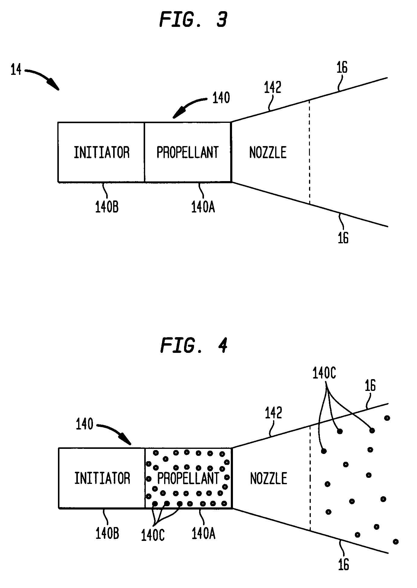
[0016]Defense system 10 includes a sensing system 12 and a rocket exhaust generator 14. The sensing system 12 and the rocket exhaust generator 14 are coupled together for purposes of communication between each other. Sensing system 12 is any system capable of detecting the approach of projectile 200, and predicting or determining trajectory 202 to...


PUM


Abstract

A projectile defense system uses a rocket exhaust generator to generate a rocket exhaust after an approaching projectile is detected / sensed. The rocket exhaust generator directs the rocket exhaust therefrom in a region that intercepts the trajectory of the approaching projectile.

Description

STATEMENT OF GOVERNMENT STATEMENT[0001]The invention described herein may be manufactured and used by or for the Government of the United States of America for government purposes without the payment of any royalties therefor.FIELD OF THE INVENTION[0002]The invention relates generally to defense systems and methods for defending a location. More particularly, the invention is a system and method for defending a location against an incoming projectile using a rocket exhaust.BACKGROUND OF THE INVENTION[0003]In a variety of world conflicts today, vehicles and structures are vulnerable to attack from inexpensive shoulder-launched projectiles / munitions such as rocket-propelled grenades (RPGs) and their variants. Propulsion for these projectiles / munitions is typically generated by either rocket motors or Davis-guns. Some have sustainer rockets to maintain or enhance flight velocity. Many have multiple warhead options designed for various threats. The most common types of warheads are shap...

Claims


Application Information

Patent Timeline
IPC IPC(8): F41H9/04F41H5/007
CPCF41H5/007F41H9/04F41H11/02F41H13/00
Inventor SANFORD, MATTHEW J.
Owner THE UNITED STATES OF AMERICA AS REPRESENTED BY THE SECRETARY OF THE NAVY
Learn More