Pneumatic actuator movement indicator

a technology of pneumatic actuators and indicators, which is applied in the direction of fluid pressure measurement, instruments, service pipes, etc., can solve the problems of not being able to read from a long distance, no available method for indicating the movement of pneumatic actuators, and feature inability to be used

Inactive Publication Date: 2008-06-17
HONEYWELL ASCA INC
View PDF14 Cites 13 Cited by
  • Summary
  • Abstract
  • Description
  • Claims
  • Application Information

AI Technical Summary

Benefits of technology

[0009]Another object of the present invention is to provide an apparatus and a method that will allow an operator to infer movement of the piston of a pneumatic actuator at a significant distance from the actuator.
[0015]If PAMI is located at the actuator end, the operator will be able to see the external indication; if a fluorescent coating is used, the operator will be able to clearly identify the movement of the piston of the pneumatic actuator by watching the movement of the indicator. Optional, Light Emitting Diode (LED) versions will allow users to infer the movement of the piston from even further distances. If PAMI is located at the Intelligent Distributed Pneumatic (IDP) controller end, the operator will be able to visualize the external indication. This location also allows the operator to diagnose the air path (leak) or the actuator from a significant distance. The operator will be able to diagnose the actuator without opening the protective beam covers. A three-magnet solution, described below, allows the device to work in any position (vertical, oblique, horizontal), making it suitable for any mounting options available on site.

Problems solved by technology

Currently, at least in many specific applications, there is no available method to indicate the movement of a pneumatic actuator other than a visual observation through a window located on the actuator body.
This feature, though, cannot be used if the actuator is in a very inaccessible area.
Also, the window cannot be read from a long distance.
As a result, any window on the actuator body is inaccessible and too far away from the operator to be used to see movement of the actuator.
Moreover, the actuator may be enclosed in a protective dust cover, which makes it even more difficult to observe movement of the actuator.

Method used


Image

  • Pneumatic actuator movement indicator
  • Pneumatic actuator movement indicator
  • Pneumatic actuator movement indicator

Examples


Embodiment Construction

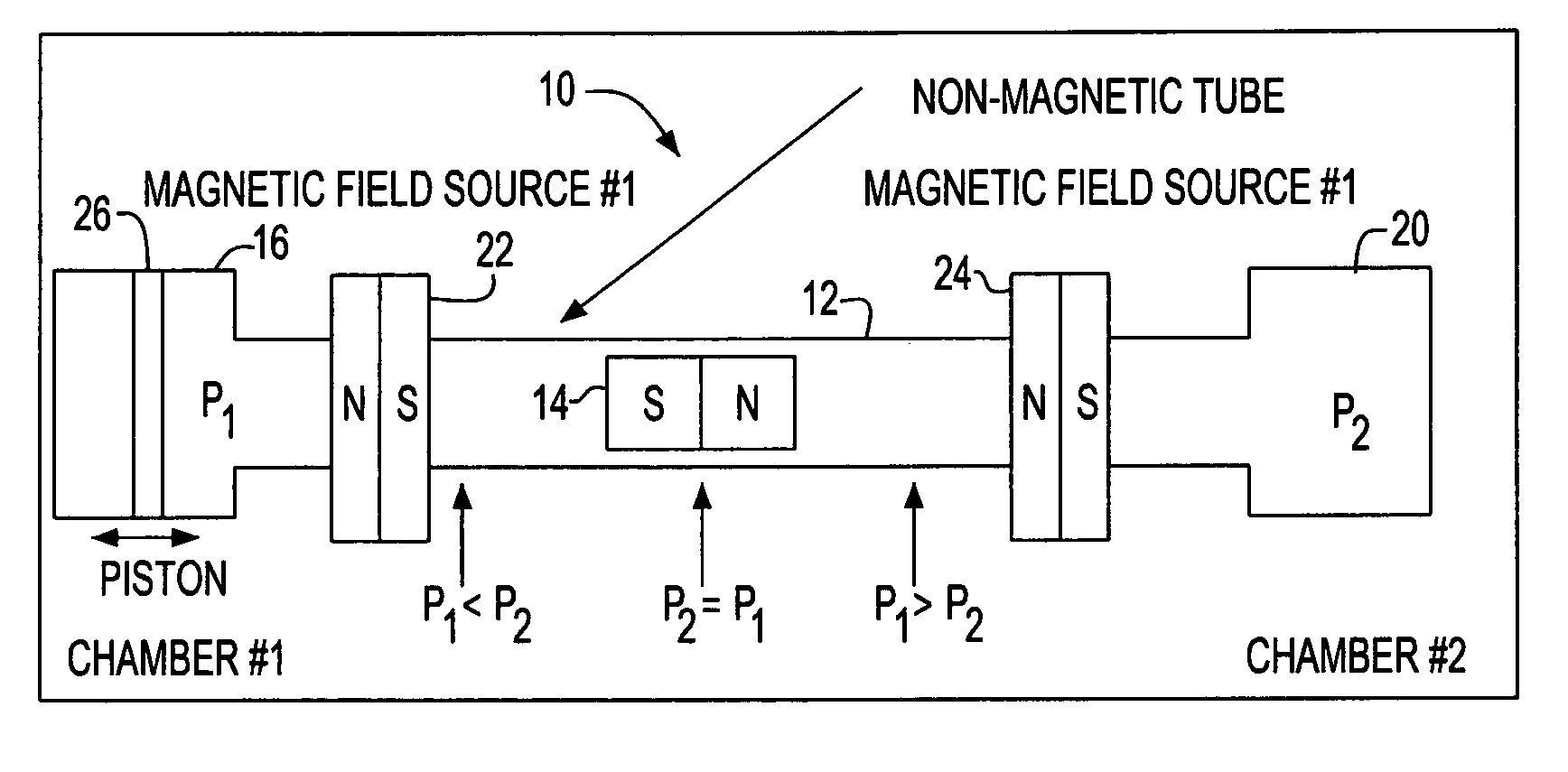
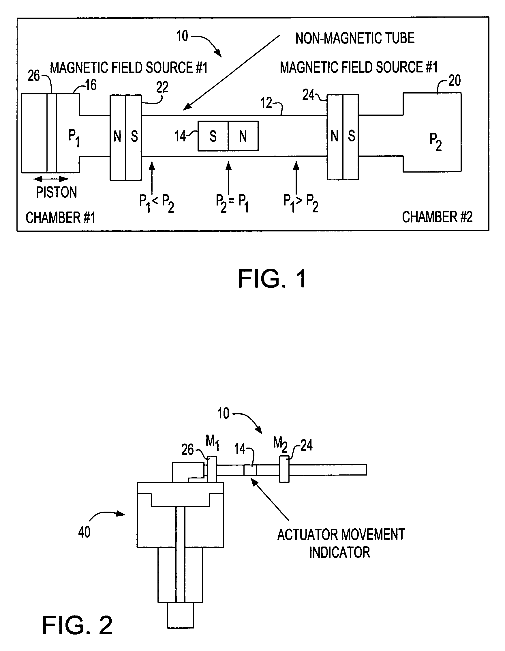
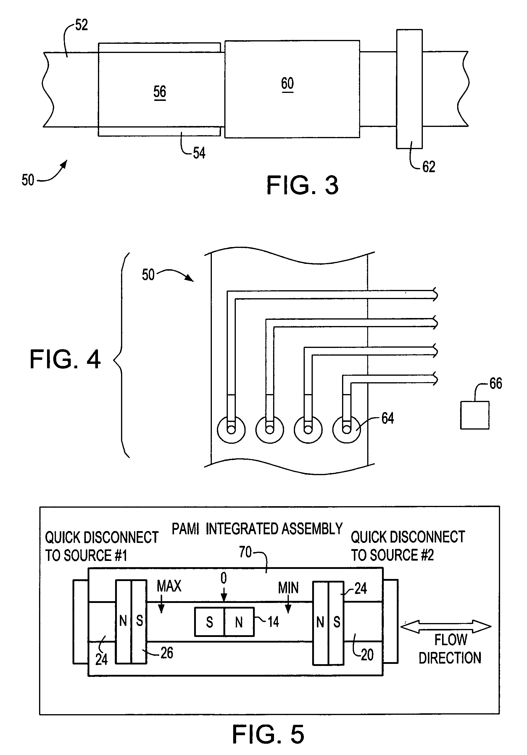
[0022]FIG. 1 shows a pneumatic actuator movement indicator (PAMI) 10 generally comprising a housing or casing 12 and an indicator 14. Housing 12, in turn, includes first and second chambers or end portions 16 and 20. Also, preferably, as illustrated in FIG. 1, indicator 14 is a magnet, and the device 10 includes additional magnets 22 and 24.

[0023]Housing chamber 16 is used to place housing 12 in fluid communication with a pneumatic actuator at a pressure P1, and housing chamber 20 is used to place housing 12 in fluid communication with a source of pressurized fluid for the pneumatic actuator at pressure P2. Indicator 14 is located in housing 12 and is movable therein in response to a difference between pressures P1 and P2. One of the housing chambers 16, 20 includes means 26 for expanding its volume, and, for instance, this means may be a piston, a bellows, or other suitable mechanism.

[0024]When device 10 is connected in place, the movement of the piston of the pneumatic actuator is...


PUM

PropertyMeasurementUnit
pressure P1aaaaaaaaaa
pressureaaaaaaaaaa
pressures P1aaaaaaaaaa

Abstract

Disclosed is a pneumatic actuator movement indicator comprising a housing adapted to be connected in series between a pneumatic actuator and a source of pressurized fluid for the actuator, and an indicator located in, and having an equilibrium position in, the housing. The housing includes a first chamber for placing the housing in fluid communication with said actuator at a pressure P1, and a second chamber for placing the housing in fluid communication with said source of pressurized fluid at a pressure P2. The indicator is movable in the housing in response to a difference between P1 and P2. Movement of the pneumatic actuator produces a difference between P1 and P2; and in response to this difference, the indicator moves away from its equilibrium position, indicating the movement of the pneumatic actuator.

Description

CROSS REFERENCE TO RELATED APPLICATION[0001]The present application claims priority from U.S. Provisional Application No. 60 / 754,768 filed on Dec. 29, 2005.BACKGROUND OF THE INVENTION[0002]1. Field of the Invention[0003]This invention generally relates to pneumatic actuators, and more specifically, relates to an apparatus and method for indicating movement of a pneumatic actuator.[0004]2. Background Art[0005]Pneumatic actuators are very cost effective actuators, and are found in many applications, such as manufacturing, aerospace, and commercial vehicles. Generally, in the operation of, for example, a linear pneumatic actuator, a high-pressure fluid is conducted to the actuator to extend or retract a piston. Movement of the piston may then be used to actuate some other mechanism such as a switch or valve.[0006]Currently, at least in many specific applications, there is no available method to indicate the movement of a pneumatic actuator other than a visual observation through a wind...

Claims


Application Information

Patent Timeline
Patent Type & Authority Patents(United States)
IPC IPC(8): G01L19/12
CPCF15B15/2807G01L9/14Y10T137/8326
Inventor ANDRONIC, CRISTIAN S.
Owner HONEYWELL ASCA INC
Why Eureka
Try Eureka