Variable frequency clock generator for synchronizing data rates between clock domains in radio frequency wireless communication systems

a clock generator and variable frequency technology, applied in the field of variable frequency clock generators for synchronizing data rates between clock domains in radio frequency wireless communication systems, can solve the problems of limiting the use of lcds primarily to lcds, unsatisfactory harmonics usually give rise to unacceptable levels of emi in high-speed digital applications, and conventional spread spectrum clock generators facilitate only one-way data transfers. , to achieve the effect of minimizing amplitud

Active Publication Date: 2008-06-17
NVIDIA CORP
View PDF5 Cites 32 Cited by
  • Summary
  • Abstract
  • Description
  • Claims
  • Application Information

AI Technical Summary

Benefits of technology

[0009]In one embodiment, the variable frequency clock signal establishes a zero direct current (“zero DC”) spectral offset for the variable frequency clock signal at the average frequency. In another embodiment, the average frequency of the range of discrete frequencies minimizes a buffer size, wherein a buffer having the buffer size is configured to transition the propagation of the data signals from being clocked by the fixed clock frequency signal to being clocked by the variable frequency clock signal. In some embodiments, an amount of data entering the buffer at a fixed data rate determined by the fixed frequency is equivalent to another amount of data exiting the buffer at the average data rate. The phase-offset controller is further configured to distribute signal energy of data signals over one or more ba

Problems solved by technology

Undesired harmonics usually give rise to unacceptable levels of EMI in high-speed digital applications, such as computer peripheral devices, consumer electronics, and embedded controller systems.
While functional, the above-described spread spectrum clock generator and its approach to minimize EMI have several drawbacks that limit their use primarily to LCDs.
One drawback is that conventional spread spectrum clock generators facilitate only one-way data transfers over connection 104.
In particular, these generators are not configured to coordinate two-way data transfers.
Another drawback is that conventional spread spectrum clock generators generally do not control the variability of the average data rate at which data arrives at the receiving end (e.g

Method used


Image

  • Variable frequency clock generator for synchronizing data rates between clock domains in radio frequency wireless communication systems
  • Variable frequency clock generator for synchronizing data rates between clock domains in radio frequency wireless communication systems
  • Variable frequency clock generator for synchronizing data rates between clock domains in radio frequency wireless communication systems

Examples


Embodiment Construction

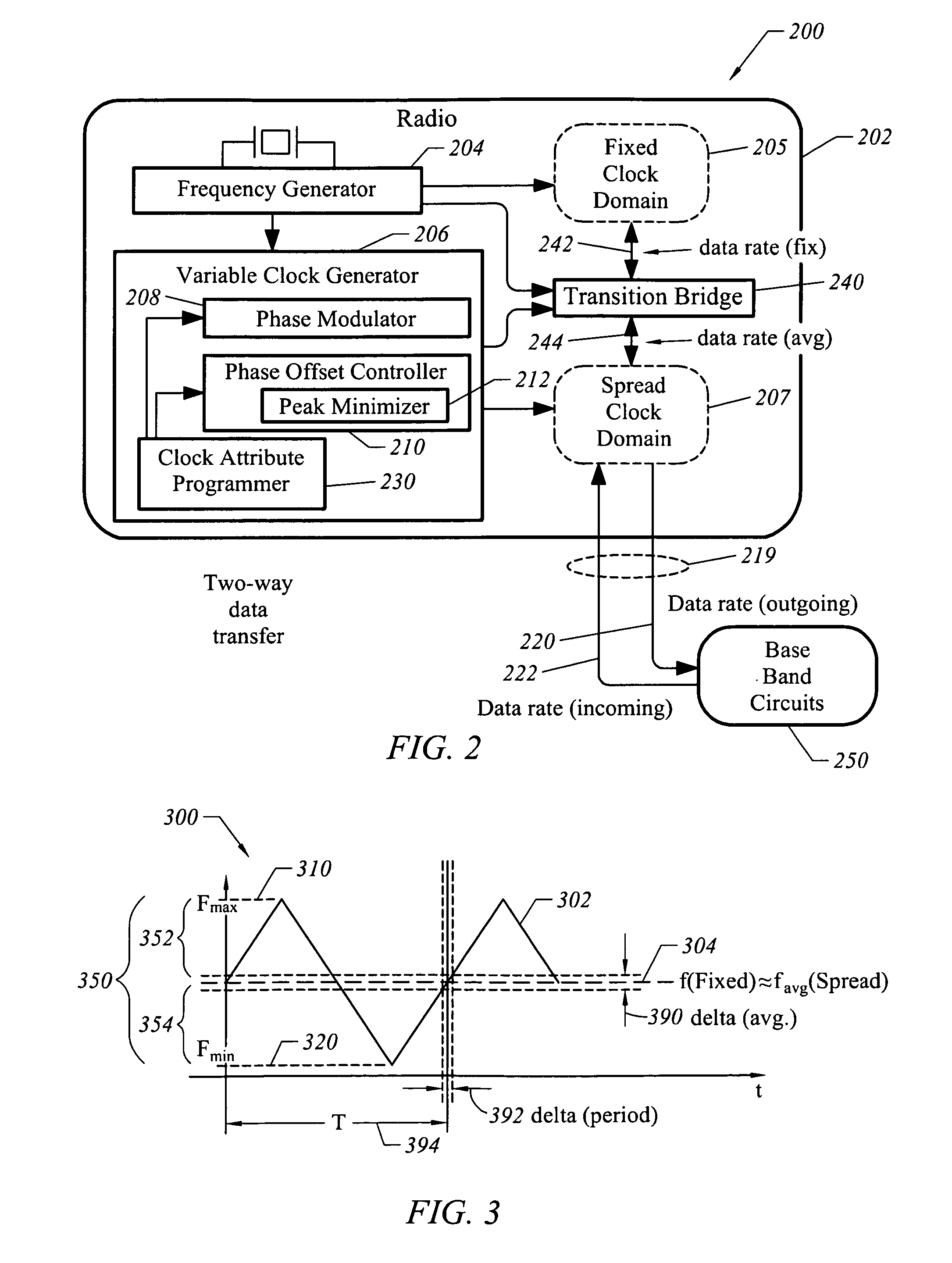
[0023]FIG. 2 illustrates an example of a radio frequency (“RF”) communications system 200 implementing a variable frequency clock generator, according to one embodiment of the present invention. RF communications system 200 includes a radio 202 that operates to transmit and / or receive wireless signals, such as radio frequency (“RF”) signals from 3 kHz to 300 GHz (including VHF, UHF, and microwave frequencies). Radio 202 also exchanges communications data via a high-speed digital link 219 with base band subsystem 250. High-speed digital link 219 reduces interfering emissions (i.e., electromagnetic interference, or “EMI”) that otherwise might violate a specific emission mask. An emission mask defines the maximum power levels over frequency during operation of RF communications system 200. As shown, radio 202 includes at least two clocks, each of which defines a separate clock domain. As to the first clock domain, a frequency generator 204 defines a fixed clock domain 205 in which a fi...


PUM


Abstract

A system, method and system are disclosed for using a variable frequency clock generator to synchronize an average data rate over intervals of time in a variable clock domain to make it equal to a fixed data rate in a fixed clock domain while reducing electromagnetic interference, among other things. In various embodiments, setting the data rates equal to each other minimizes storage used to transition data signals between clock domains. In one embodiment, a variable frequency clock generator includes a phase modulator configured to form a variable frequency clock. Also, the variable clock generator is configured to maintain an average frequency over specific periods of time for the range of discrete frequencies. The phase-offset controller sets an average clock having substantially no offset between a fixed data rate in the fixed clock domain and an average data rate in the variable clock domain.

Description

CROSS REFERENCE TO RELATED APPLICATION[0001]This application claims the benefit of U.S. Provisional Application No. 60 / 647,077, entitled “Spread Spectrum Link Using a Spread Spectrum Clock for Wireless Communications” and filed on Jan. 24, 2005, the disclosure of which is incorporated herein by reference in its entirety.BRIEF DESCRIPTION OF THE INVENTION[0002]This invention relates generally to wireless communications, and more particularly, to a variable frequency clock generator for exchanging digitized communications data via a high-speed digital link while producing reduced electromagnetic interference (“EMI”), the high-speed digital link being composed of unshielded conductors, for example. In one embodiment, the variable frequency clock generator synchronizes an average data rate for a variable clock domain over an interval of time with a fixed data rate for a fixed clock domain. This at least minimizes an amount of temporary storage for transitioning digitized communications ...

Claims


Application Information

Patent Timeline
IPC IPC(8): H04B1/06
CPCH04B15/02H04B2215/067
Inventor LIU, TAOKERAMAT, MANSOURLIU, EDWARD WAI YEUNGHESHAMI, MEHRDADKUO, TIMOTHY C.
Owner NVIDIA CORP
Why Eureka
Try Eureka