IC with linking module in series with TAP circuitry

a technology of tap circuitry and linking modules, applied in the field of integrated circuits, can solve problems such as unnecessarily complex access to testing, in-circuit emulation, and/or in-circuit programming functions associated with one of the individual tap domains

Inactive Publication Date: 2008-06-17
TEXAS INSTR INC
View PDF4 Cites 8 Cited by
  • Summary
  • Abstract
  • Description
  • Claims
  • Application Information

AI Technical Summary

Problems solved by technology

One drawback of the TAP domain arrangement of FIG. 3 is that it does not comply with the IEEE 1149.1 standard, since, according to the rules of that standard, only the ICs TAP domain should be present between TDI and TDO when the IC is initially powered up.
A second drawback of the TAP domain arrangement of FIG. 3 is that it may lead to unnecessarily complex access for testing, in-circuit emulation, and / or in-circuit programming functions associated with ones of the individual TAP domains.

Method used


Image

  • IC with linking module in series with TAP circuitry
  • IC with linking module in series with TAP circuitry
  • IC with linking module in series with TAP circuitry

Examples


Embodiment Construction

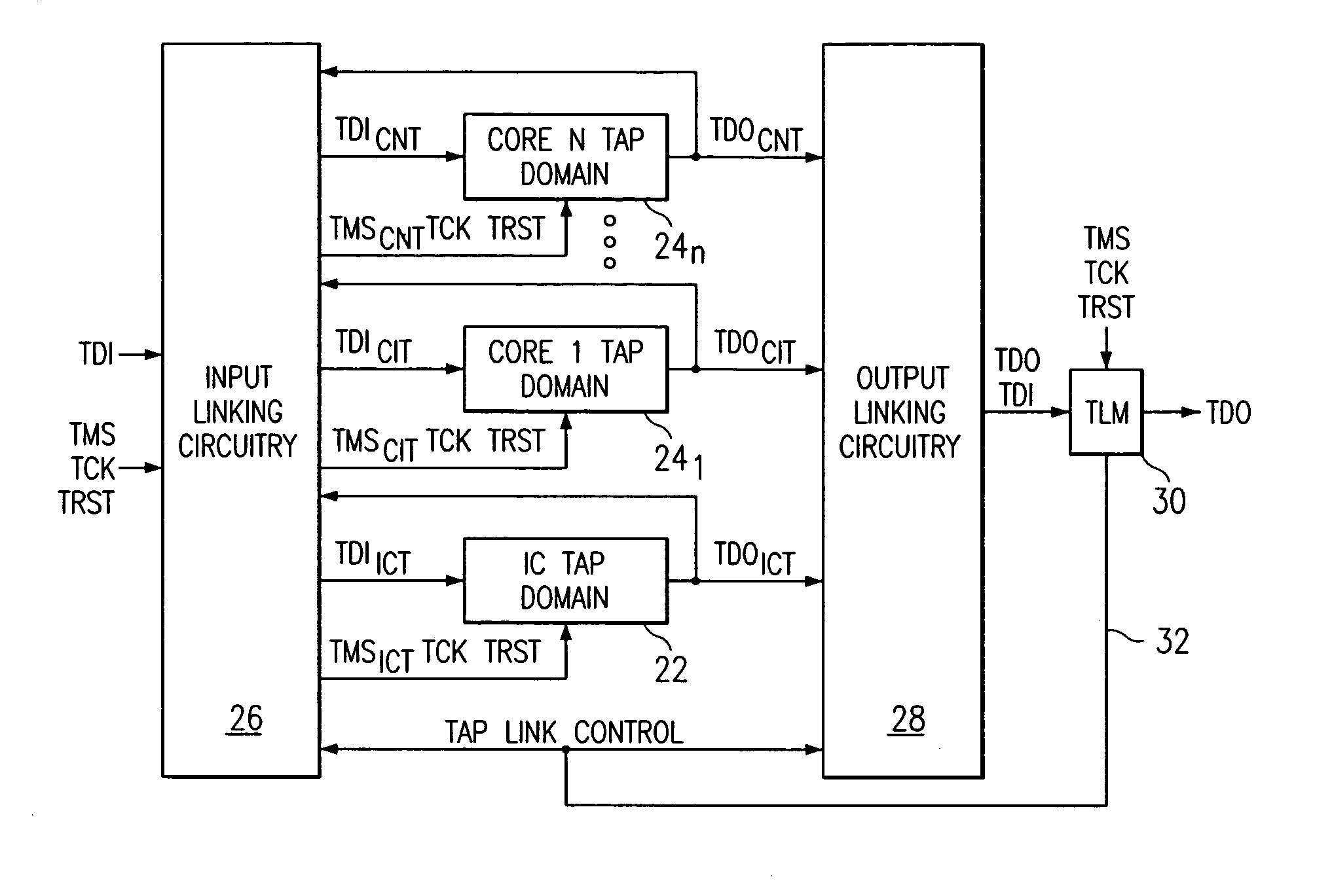
[0023]FIG. 4 illustrates the preferred structure for connecting multiple TAP domains within an IC according to the present invention. The structure of the present invention includes input linking circuitry 26 and output linking circuitry 28 for connecting any one or more TAP domains to the ICs TDI, TDO, TMS, TCK and TRST pins, and a TAP Linking Module (TLM) 30 circuit for providing the control to operate the input and output linking circuitry. The concept of input and output linking circuitry and use of a TLM circuit to control the input and output linking circuitry is disclosed in application Ser. No. 08 / 918,872, filed Aug. 26, 1999, now U.S. Pat. No. 6,073,254.

[0024]The input linking circuitry 26 receives as input; (1) the TDI, TMS, TCK, and TRST IC pins signals, (2) the TDO outputs from the IC TAP (ICT) domain 22 (TDOICT), the Core 1 TAP (CIT) domain 241 (TDOCIT), and the Core N TAP (CNT) domain 24n (TDOCNT), and (3) TAP link control input from the TLM 30. The TCK and TRST inputs...


PUM


Abstract

IEEE 1149.1 Test Access Ports (TAPs) may be utilized at both IC and intellectual property core design levels. TAPs serve as serial communication ports for accessing a variety of embedded circuitry within ICs and cores including; IEEE 1149.1 boundary scan circuitry, built in test circuitry, internal scan circuitry, IEEE 1149.4 mixed signal test circuitry, IEEE P5001 in-circuit emulation circuitry, and IEEE P1532 in-system programming circuitry. Selectable access to TAPs within ICs is desirable since in many instances being able to access only the desired TAP(s) leads to improvements in the way testing, emulation, and programming may be performed within an IC. A TAP linking module is described that allows TAPs embedded within an IC to be selectively accessed using 1149.1 instruction scan operations.

Description

[0001]This application is a divisional of application Ser. No. 09 / 864,509, filed May 24, 2001, now U.S. Pat. No. 7,058,862;[0002]which claims priority under 35 USC 119(e)(1) of provisional application Ser. No. 60 / 207,691, filed May 26, 2000.CROSS REFERENCE TO RELATED APPLICATIONS[0003]This application is related to 1) application Ser. No. 08 / 918,872, filed Aug. 26, 1999, now U.S. Pat. No. 6,073,254, “Selectively Accessing Test Access Ports in a Multiple Test Access Port Environment”, which is hereby incorporated by reference, 2) application Ser. No. 09 / 458,313, filed Dec. 10, 1999, now U.S. Pat. No. 6,324,614, “Selectively Accessing Test Access Ports in a Multiple Test Access Port Environment”, which is hereby incorporated by reference, and 3) application Ser. No. 09 / 277,504, filed Mar. 26, 1999, now U.S. Pat. No. 6,324,662, “A TAP and Linking Module for Scan Access of Multiple Cores with 1149.1 Test Access Ports”, which is hereby incorporated by reference.FIELD OF THE INVENTION[000...

Claims


Application Information

Patent Timeline
Patent Type & Authority Patents(United States)
IPC IPC(8): G01R31/28G01R31/3185
CPCG01R31/3177G01R31/318555G01R31/31727
Inventor WHETSEL, LEE D.HAROUN, BAHER S.LASHER, BRIAN J.KINRA, ANJALI
Owner TEXAS INSTR INC
Why Eureka
Try Eureka