Biosensing device

a biosensing device and biosensing technology, applied in the field of biosensing devices, can solve the problems of inexhaustible above-mentioned biosensing devices and still inability to execute procedures on bisensing devices

Inactive Publication Date: 2008-01-17
EPS BIO TECH CORP
View PDF6 Cites 2 Cited by
  • Summary
  • Abstract
  • Description
  • Claims
  • Application Information

AI Technical Summary

Benefits of technology

[0008]According to an embodiment of the present invention, a biosensing device for measuring a testing strip to generate a measurement result is disclosed. The biosensing device comprises: a sensors and actuators group; a processing module comprising: a storage device storing an application software; and a processing unit, electrically connected to the storage device; a routing matrix, comprising a plurality of connecting ends and a plurality of switch devices, the plurality of connecting ends are respectively electrically connected to the testing strip, the processing module, and the sensors and actuators group; and an in-system programming interface, electrically connected to the processing module, for connecting to an in-system programmer to utilize the in-system programmer to update the application software; wherein the processing unit executes the updated application software updated by the in-system programmer to control the plurality of switch devices inside the routing matrix to change electrical connections among the sensors and actuators group, the processing module, and the testing strip in order to utilize the sensors and actuators group to measure the testing strip and process a sensing result of the sensors and actuators group to generate the measuring result.

Problems solved by technology

But the adjusting mechanism only allows the user to select one of previously arranged procedures or determine the parameter utilized in the operations.
In other words, even the above-mentioned biosensing device can utilize a ROM key, the bisensing device still cannot execute the procedures, which are not previously embedded inside the memory.
That is, the above-mentioned biosensing device is not expandable.

Method used


Image

  • Biosensing device
  • Biosensing device
  • Biosensing device

Examples


Embodiment Construction

[0013]The “TITLE” of the invention will be described with reference to the accompanying drawings.

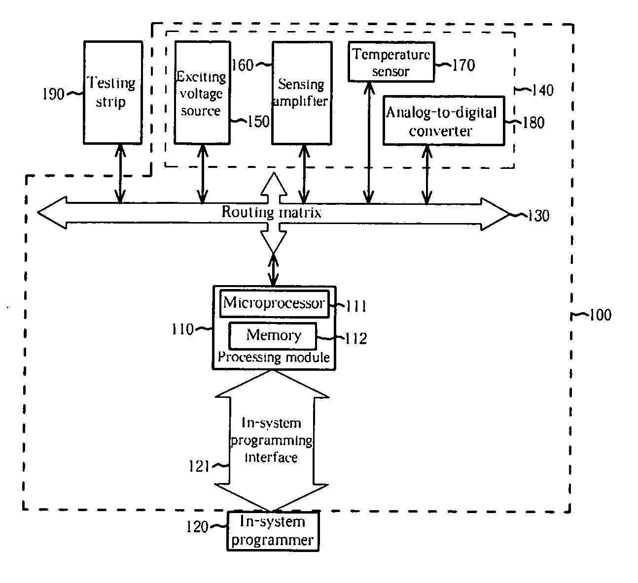
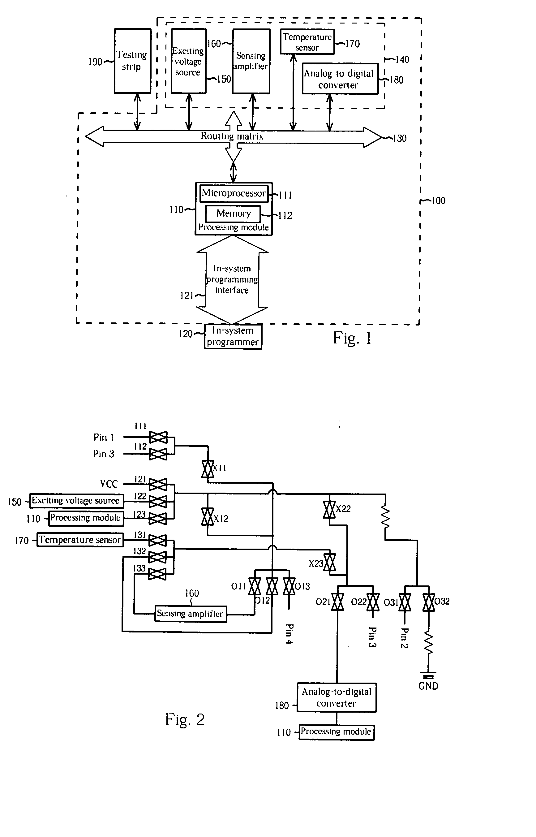
[0014]Please refer to FIG. 1, which is a diagram of a biosensing device 100 of an embodiment according to the present invention. As shown in FIG. 1, the biosensing device 100 comprises a processing module 110, an in-system programming interface 121, a routing matrix 130, and a sensors and actuators group 140. The sensors and actuators group 140 comprises an exciting voltage source 150, a sensing amplifier 160, a temperature sensor 170, and an analog-to-digital converter 180.

[0015]In addition, the processing module 110 comprises a microprocessor 111 and a memory 112 electrically connected to the microprocessor 111. The memory 112 stores application software. Please note that, the processing module 110, the exciting voltage source 150, the sensing amplifier 160, the temperature sensor 170, the A / D converter 180, and a testing strip 190 to be measured are respectively electrically connected...


PUM

PropertyMeasurementUnit
temperatureaaaaaaaaaa
concentrationaaaaaaaaaa
flexibleaaaaaaaaaa

Abstract

A biosensing device includes: a routing matrix, electrically connected to a testing strip; a sensors and actuators group, electrically connected to the routing matrix; a processing module, electrically connected to the routing matrix, and an in-system programming interface. The processing module includes a processing unit and a storage device storing application software. The in-system programming interface is electrically connected to the processing module, for connecting to an external in-system programmer and utilizing the in-system programmer to update the application software; wherein the processing unit executes the application software, updated through in-system programming interface, to control the sensors and actuators group for measuring the testing strip to generate a biosensing result.

Description

BACKGROUND OF THE INVENTION[0001]1. Field of the Invention[0002]The present invention relates to a biosensing device, and more particularly, to a biosensing device, which has an in-system programming interface, capable of utilizing an external in-system programmer through the in-system programming interface in order to arrange the inner components of the biosensing device such that different functions can be achieved or different algorithms can be executed.[0003]1. Description of the Related Art[0004]In general, a biosensing device is utilized to measure the concentration of biological materials (for example, blood glucose concentration) in humans' blood. Therefore, a diabetic can monitor his blood glucose concentration by using the biosensing device to maintain his health.[0005]U.S. Pat. No. 5,366,609 discloses a biosensing device, which utilizes a read-only-memory key (ROM key) to select a specific biosensing procedure to be executed or to provide parameters for biosensing procedu...

Claims


Application Information

Patent Timeline
Patent Type & Authority Applications(United States)
IPC IPC(8): G01N21/00
CPCG01N21/8483
Inventor CHIU, MURPHYYUAN, WEN CHING
Owner EPS BIO TECH CORP
Why Eureka
Try Eureka