Low pressure measurement devices in high pressure environments

a high-pressure environment and low-pressure measurement technology, applied in the field of biomedical technology, can solve the problems of reducing reliability, requiring close manufacturing tolerances, and unable to tolerate even moderate injection pressure of pressure transducers designed for physiological measurements

Inactive Publication Date: 2008-06-24
ACIST MEDICAL SYST
View PDF104 Cites 44 Cited by
  • Summary
  • Abstract
  • Description
  • Claims
  • Application Information

AI Technical Summary

Benefits of technology

[0007]The present invention presents various novel approaches to solving the problems inherent in measuring biological pressures in high pressure systems. To protect a pressure transducer exposed to fluid flows at higher pressures than its overpressure rating, a novel valve is used that closes a protected leg in which the transducer is located. The various exemplary embodiments of such valves each have a high pressure input, one or more low pressure inputs, and an output. In operation, when a high pressure fluid flow occurs at a high pressure input, the valve automatically closes the low pressure inputs. Alternatively, a novel transducer system is presented, which automatically limits the effective pressure sensed by a transducer to a certain maximum.

Problems solved by technology

Generally, pressure transducers that are designed for physiological measurements cannot tolerate even moderate injection pressures and therefore must be isolated from the fluid path during a high-pressure injection.
However, such manifolds also require close manufacturing tolerances, are generally expensive, and are designed for use in permanent installations.
Such polymers have a drawback; they are less conducive to a consistent fit between different parts, which tends to decrease reliability.
No device currently exists that combines low cost and ease of manufacture and use with the high pressure capability of industrial valves.
In addition, devices adapted to measure high pressures which would, by definition, be capable of withstanding those pressures, are simply not sensitive enough to accurately measure physiological pressures.
Thus, in the example discussed above, a physician performing an angiography using only a high-pressure sensor could, in fact, monitor the injection pressure while contrast material is being injected, but would have no way of monitoring the patient's blood pressure when no injection is occurring.

Method used


Image

  • Low pressure measurement devices in high pressure environments
  • Low pressure measurement devices in high pressure environments
  • Low pressure measurement devices in high pressure environments

Examples


embodiment

Disc Valve Embodiment

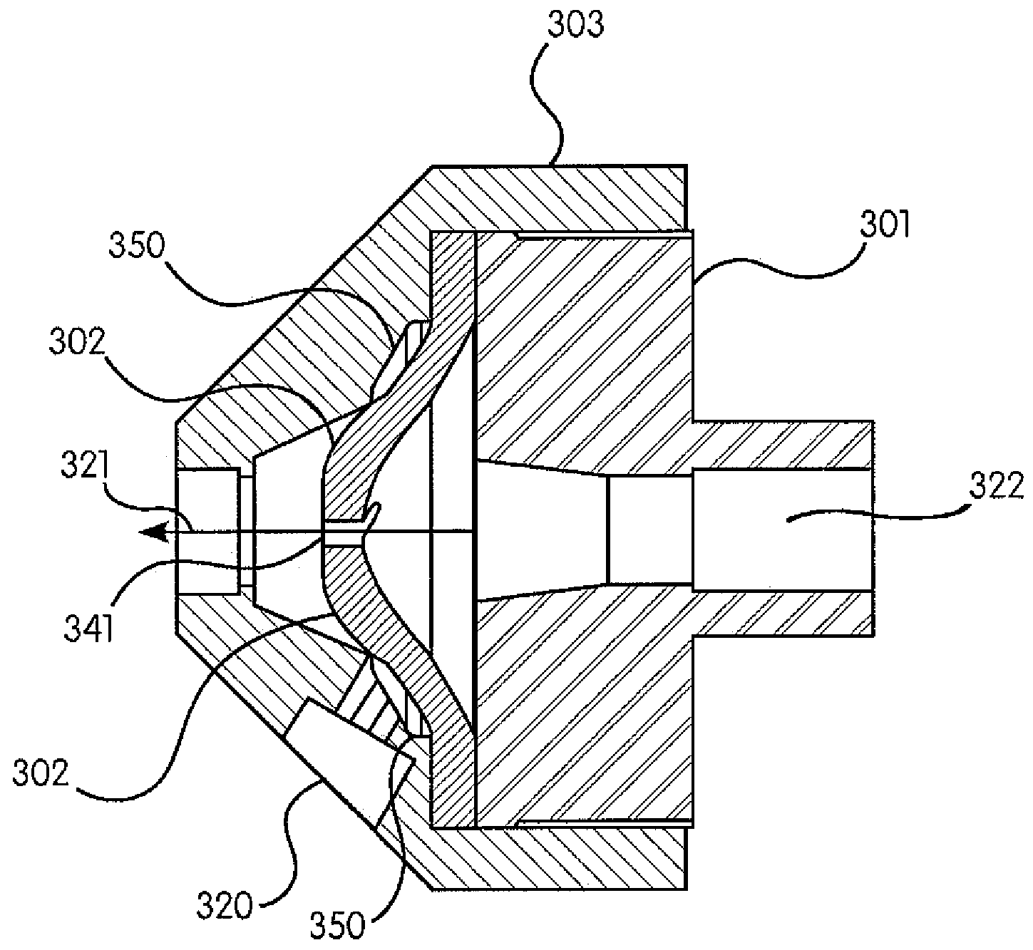
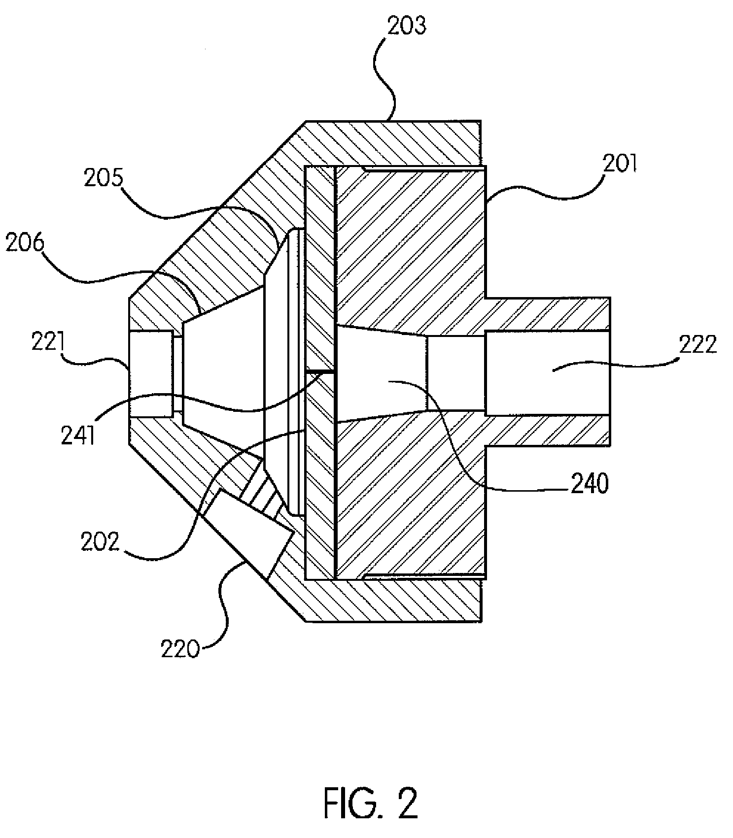
[0036]It is within the objects of the present invention to provide a valve that is inexpensive, reliable, biocompatible, non-allergenic and able to withstand pressures up to 1500 psi. Moreover, the valve must be able to withstand several modes of sterilization (gamma irradiation, ethylene oxide and e-beam) as well as have a clear housing. It must be easy to remove all bubbles when it is flushed with saline or contrast. The pressure gradients required in the valve are complex. It must have a reliable cracking pressure above 9 psi and, upon opening, ensure that an attached pressure gauge (generally, but not always, located in the saline port, as described below) is never exposed to pressures above approximately 15 psi (1 atm). To achieve this, because generally a pressure sensing connection is very ‘stiff’, parts of the valve must not project or bulge into the sensing path even at very high pressure conditions. Finally, the components of the valve must not degrade...


PUM

PropertyMeasurementUnit
pressuresaaaaaaaaaa
pressuresaaaaaaaaaa
pressuresaaaaaaaaaa

Abstract

The present invention presents various novel approaches to solving the problems inherent in measuring biological pressures in high pressure systems. Thus, to protect a pressure transducer exposed to fluid flows at higher pressures than its overpressure rating, a novel valve is used that closes a protected leg in which the transducer is located. The various exemplary embodiments of such valves each have a high pressure input, one or more low pressure inputs, and an output. In operation, when a high pressure fluid flow occurs at a high pressure input, such valves automatically close the low pressure inputs. Alternatively, a novel transducer system is presented, which automatically limits the effective pressure sensed by a transducer to a certain maximum.

Description

CROSS REFERENCE TO OTHER APPLICATIONS[0001]This application claims the benefit of U.S. Provisional Patent Application Ser. Nos. 60 / 338,859 and 60 / 338,883, each filed on Dec. 7, 2001.FIELD OF THE INVENTION[0002]This invention relates to the field of biomedical technology and, in particular, to methods, systems and apparatus for protecting biological pressure measurement devices in high fluid pressure environments.BACKGROUND OF THE INVENTION[0003]Certain medical procedures, such as, for example, contrast media injections during cardiological procedures, can require that liquids (such as radiographic contrast agents in, for example, angiography) be injected into a patient's system under high pressures. Such pressures are commonly as high as 1200 lb / in2 (psi) or more than 60,000 mm Hg. While performing such procedures it is also desirable to measure the patient's biological pressures. For example, in angiography it is desirable to record the much lower intravascular and intracardiac pre...

Claims


Application Information

Patent Timeline
Patent Type & Authority Patents(United States)
IPC IPC(8): F16K15/14A61B5/00A61B5/02A61B5/0215A61B5/103A61B5/117F16K31/12G01L
CPCA61B5/0215A61B5/411A61M39/22F16K15/147Y10T29/49405A61M5/007Y10T137/7879Y10T137/7881Y10T137/784Y10T137/7843Y10T137/2567Y10T137/87676Y10T137/0318F16K15/144F16K15/1402
Inventor WILSON, ROBERT F.DUCHON, DOUGLAS J.GABBARD, MARKMOHIUDDIN, KHADERMCPEAK, THOMAS
Owner ACIST MEDICAL SYST
Why Eureka
Try Eureka