
Variable-shape mirror and optical pickup device therewith

a mirror and variable shape technology, applied in the field of variable shape mirrors, can solve the problems of not always remaining perpendicular, not being able to accurately write or read information, and not being able to correct aberrations properly, so as to increase the shape variation of the mirror surface, and vary the shape of the mirror surface more uniformly

Inactive Publication Date: 2008-06-24
FUNAI ELECTRIC CO LTD
View PDF3 Cites 5 Cited by
  • Summary
  • Abstract
  • Description
  • Claims
  • Application Information

AI Technical Summary

Benefits of technology

The present invention provides a variable-shape mirror that can correct aberrations without being affected by deformation on the mirror surface. The mirror has a support base, a mirror portion, fixed portions, and piezoelectric elements. The piezoelectric elements are arranged closer to the center of the mirror portion than the fixed portions and can vary the shape of the mirror surface. This helps to properly correct aberrations. The fixed portions are bonded to the mirror portion at an edge thereof, which increases the shape variation of the mirror surface with a small amount of displacement of the piezoelectric elements. The piezoelectric elements are arranged outside an area within which the mirror surface is irradiated with the light beam, which prevents deformation on the mirror surface. The individual pairs of fixed portions and piezoelectric elements are arranged symmetrically in cross-shaped directions, which makes it possible to vary the shape of the mirror surface more uniformly and correct aberrations more properly. The optical pickup device according to the present invention is provided with the variable-shape mirror, which prevents deformation on the mirror surface and achieves a wide degree of aberration correction.

Problems solved by technology

In reality, however, when the disc is rotating, their relationship does not always remain perpendicular.
When coma aberration is produced, the spot of laser light shone on the optical disc deviates from the proper position, and, when the coma aberration becomes larger than permitted, inconveniently, it becomes impossible to accurately write or read information.
Consequently, it may not be possible to properly correct aberrations.

Method used


Image

  • Variable-shape mirror and optical pickup device therewith
  • Variable-shape mirror and optical pickup device therewith
  • Variable-shape mirror and optical pickup device therewith

Examples


Embodiment Construction

[0035]Hereinafter, embodiments of the present invention will be described with reference to the accompanying drawings. It should be understood that the embodiments described below are merely examples, and are therefore not meant to limit in any way the manner in which the present invention can be carried. It should also be understood that, in the drawings, the sizes and thicknesses of the components, the amount of displacement that takes place when the shape is varied, etc. are exaggerated for the purpose of easy understanding, and therefore these dimensions are different from those actually observed.

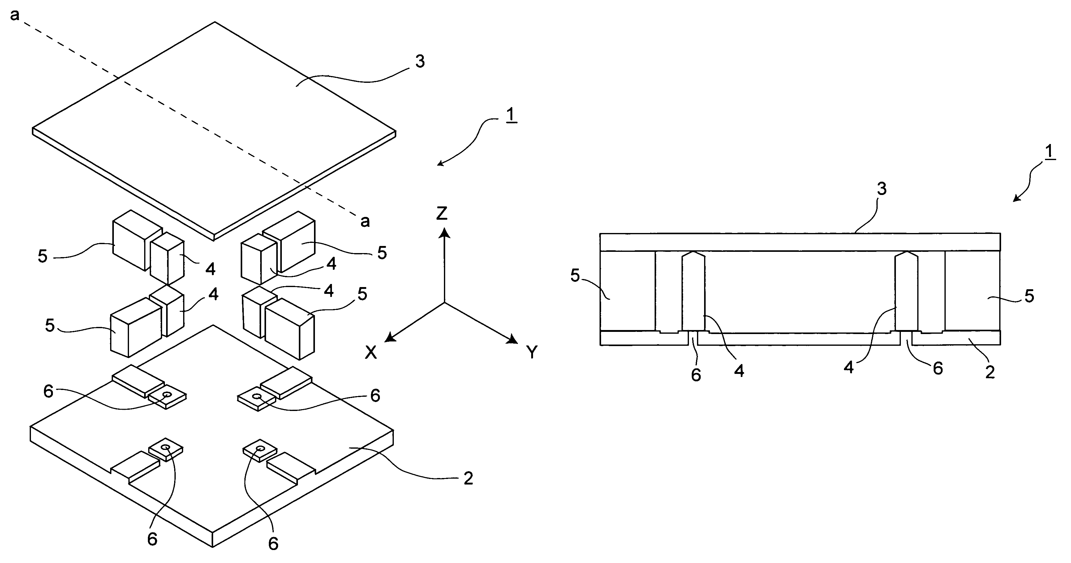
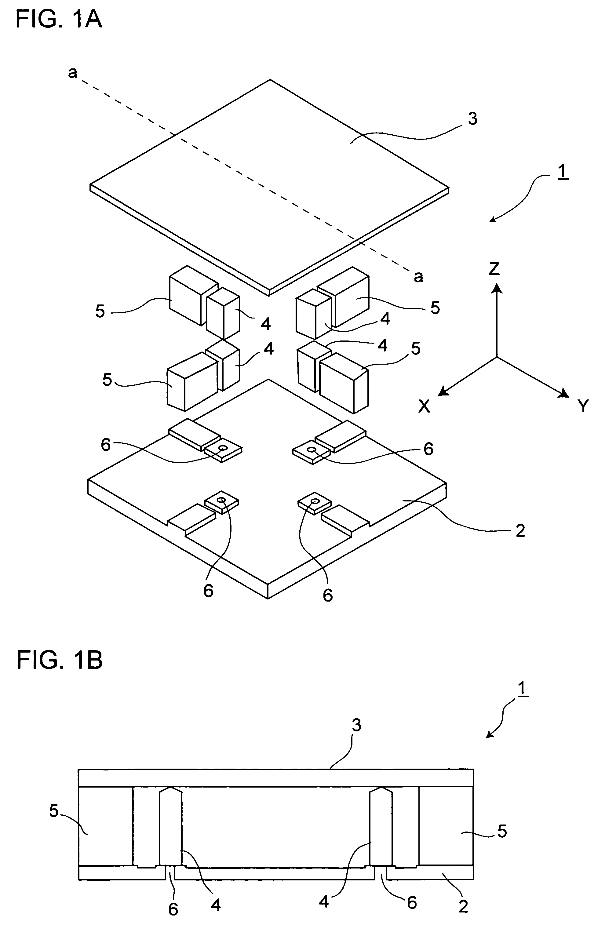
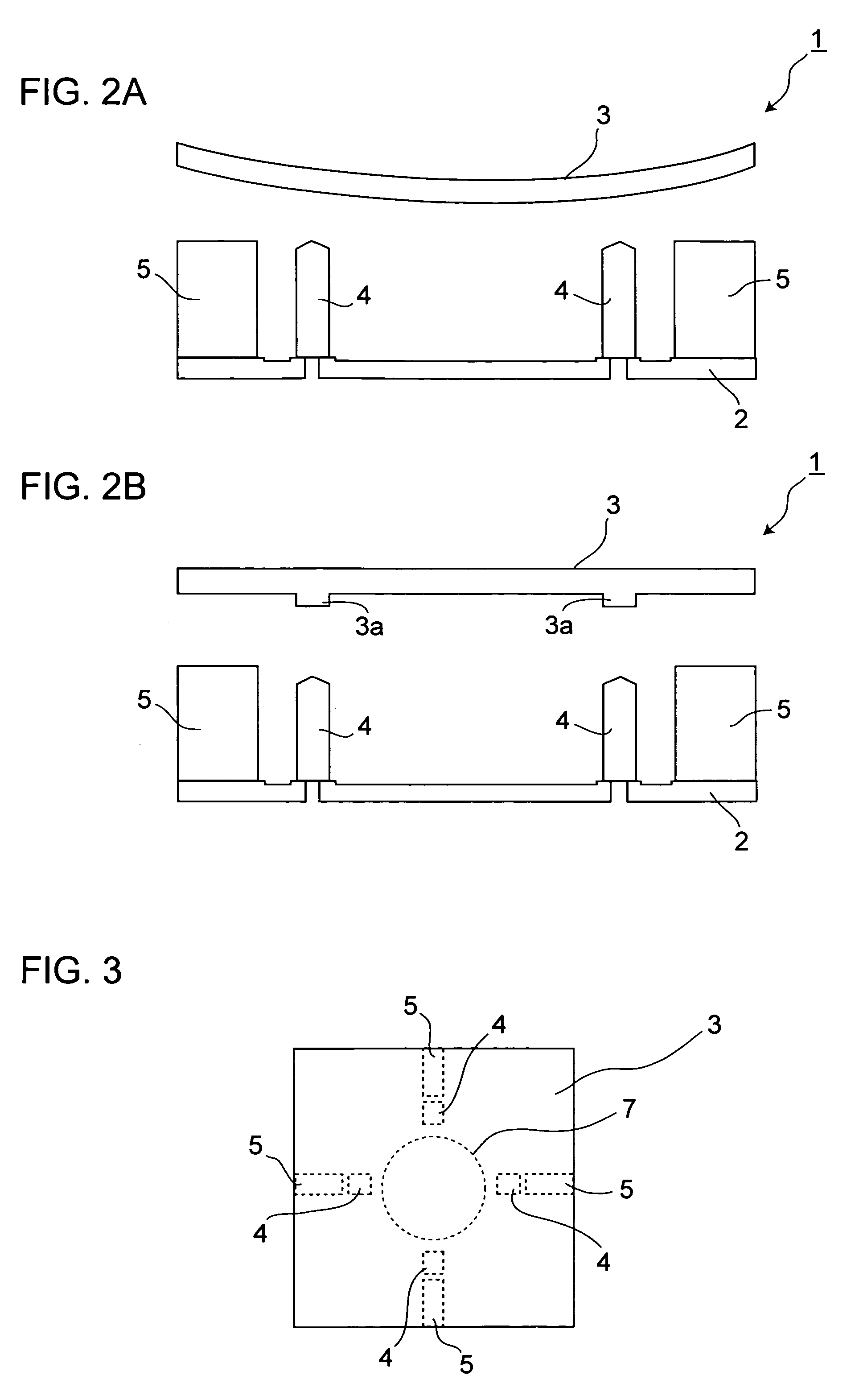
[0036]FIG. 1A is an exploded perspective view showing components constituting a variable-shape mirror embodying the invention. FIG. 1B is a sectional view as cut along line a-a shown in FIG. 1A, showing a state in which all of the components are put together.

[0037]A variable-shape mirror 1 according to the present invention is built as an abberation correcting mirror that varies the sha...


PUM


Abstract

A variable-shape mirror is provided with: a support base; a mirror portion that is disposed to face the support base and that has, on a side thereof facing away from the support base, a mirror surface which is irradiated with a light beam; fixed portions that fix the mirror portion to the support base; and piezoelectric elements that are sandwiched between the support base and the mirror portion and that vary a shape of the mirror surface. Here, the piezoelectric elements are arranged closer to a center of the mirror portion than the fixed portions are.

Description

[0001]This application is based on Japanese Patent Application No. 2005-179447 filed on Jun. 20, 2005, the contents of which are hereby incorporated by reference.BACKGROUND OF THE INVENTION[0002]1. Field of the Invention[0003]The present invention relates to a variable-shape mirror that permits the shape of a mirror surface thereof to be varied, and more particularly relates to the structure thereof. The present invention also relates to an optical pickup device provided with such a variable-shape mirror.[0004]2. Description of Related Art[0005]When information is read from or written to an optical disc such as a CD (compact disc) or DVD (digital versatile disc) by the use of an optical pickup device, the relationship between the optical axis of the optical pickup device and the disc surface should ideally be perpendicular. In reality, however, when the disc is rotating, their relationship does not always remain perpendicular. As a result, with an optical disc such as a CD or DVD, w...

Claims


Application Information

Patent Timeline
Patent Type & Authority Patents(United States)
IPC IPC(8): G02B5/08
CPCG02B26/0825G11B7/1362G11B7/13927
Inventor NAGASHIMA, KENJIFUJII, HITOSHITANAKA, FUMINORISUGIYAMA, SUSUMUISHII, AKIRATANAKA, KATSUHIKOKUZE, WATARU
Owner FUNAI ELECTRIC CO LTD
Learn More