Hand-held power tool with an auxiliary handle

a technology of auxiliary handle and power tool, which is applied in the field of hand-held power tools, can solve the problems of poor tool handling, large manufacturing cost, and rapid fatigue of operators, and achieve the effects of reducing manufacturing costs, facilitating repositioning of side handles, and facilitating the handling of side handles

Inactive Publication Date: 2008-07-01
HILTI AG
View PDF27 Cites 16 Cited by
  • Summary
  • Abstract
  • Description
  • Claims
  • Application Information

AI Technical Summary

Benefits of technology

[0010]The provision of two support points permits a very stable attachment of the side handle to the housing. The two support points provide for a relatively large pivot region of the support member, which can expand positioning possibilities of the side handle. Due to a locking connection of the support member with the housing, only small vibrations are applied to a side handle. Altogether, with the support member being supported at two pivot points, a comfortable holding of a power tool in all applications is achieved.
[0024]It is further advantageous when the side handle has a knob shape. This insures a particularly comfortable two-hand guidance of the power tool.

Problems solved by technology

The drawback of the known solution consists in that the connection of the support and the housing should withstand large forces and, at the same time, should insure variable positions of the support.
This involves relatively large manufacturing costs.
In addition, with so supported side handles, during the operation, relatively strong vibrations are transmitted to the hand of the operator, which leads to a poor handling of the tool and to a rapid fatigue of the operator.
Further in some applications, e.g., grinding, because of a sidewise projecting support, no optimal gripping or holding of the tool is achieved that would have permitted to comfortably apply high press-on forces.

Method used


Image

  • Hand-held power tool with an auxiliary handle
  • Hand-held power tool with an auxiliary handle
  • Hand-held power tool with an auxiliary handle

Examples


Embodiment Construction

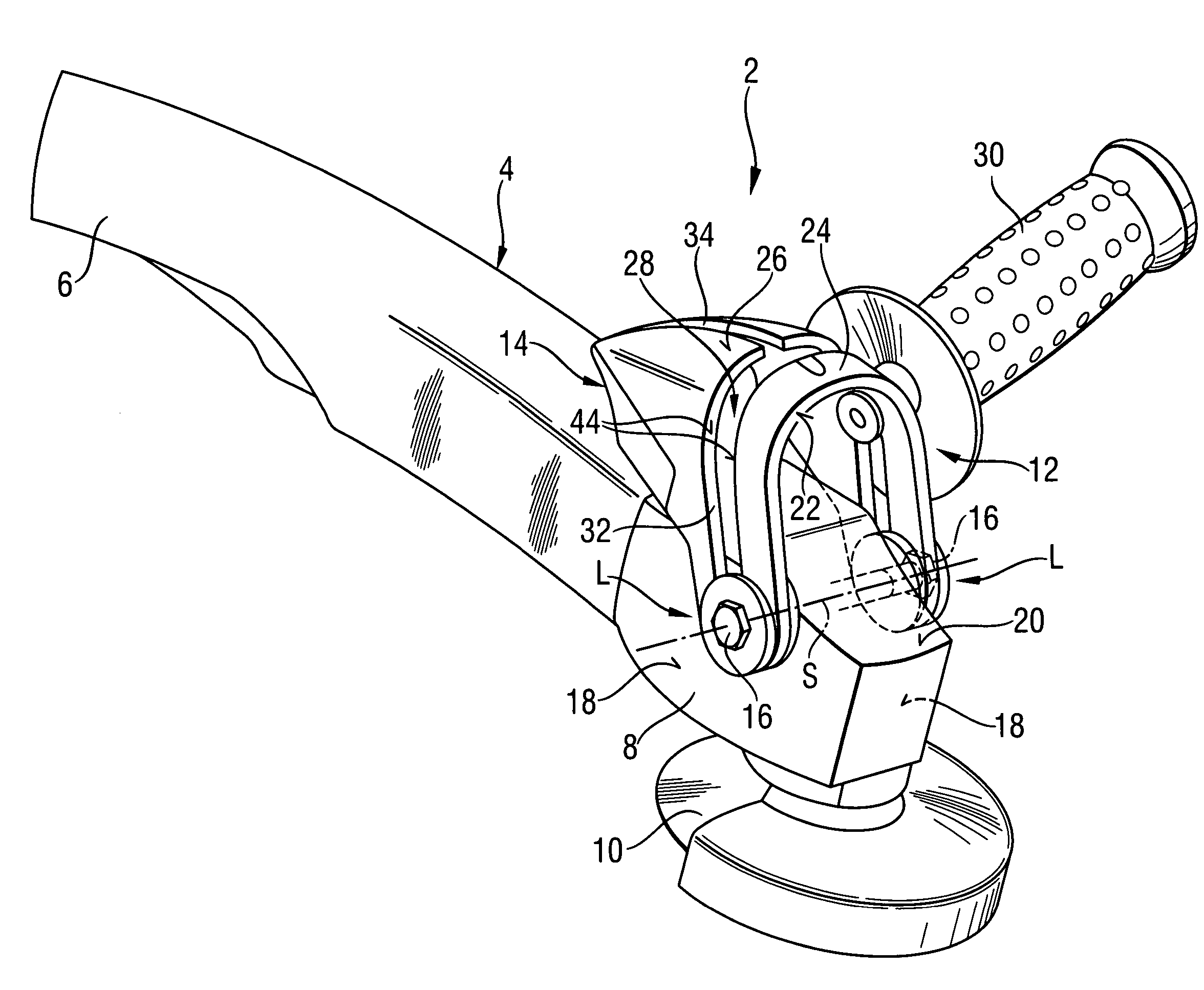
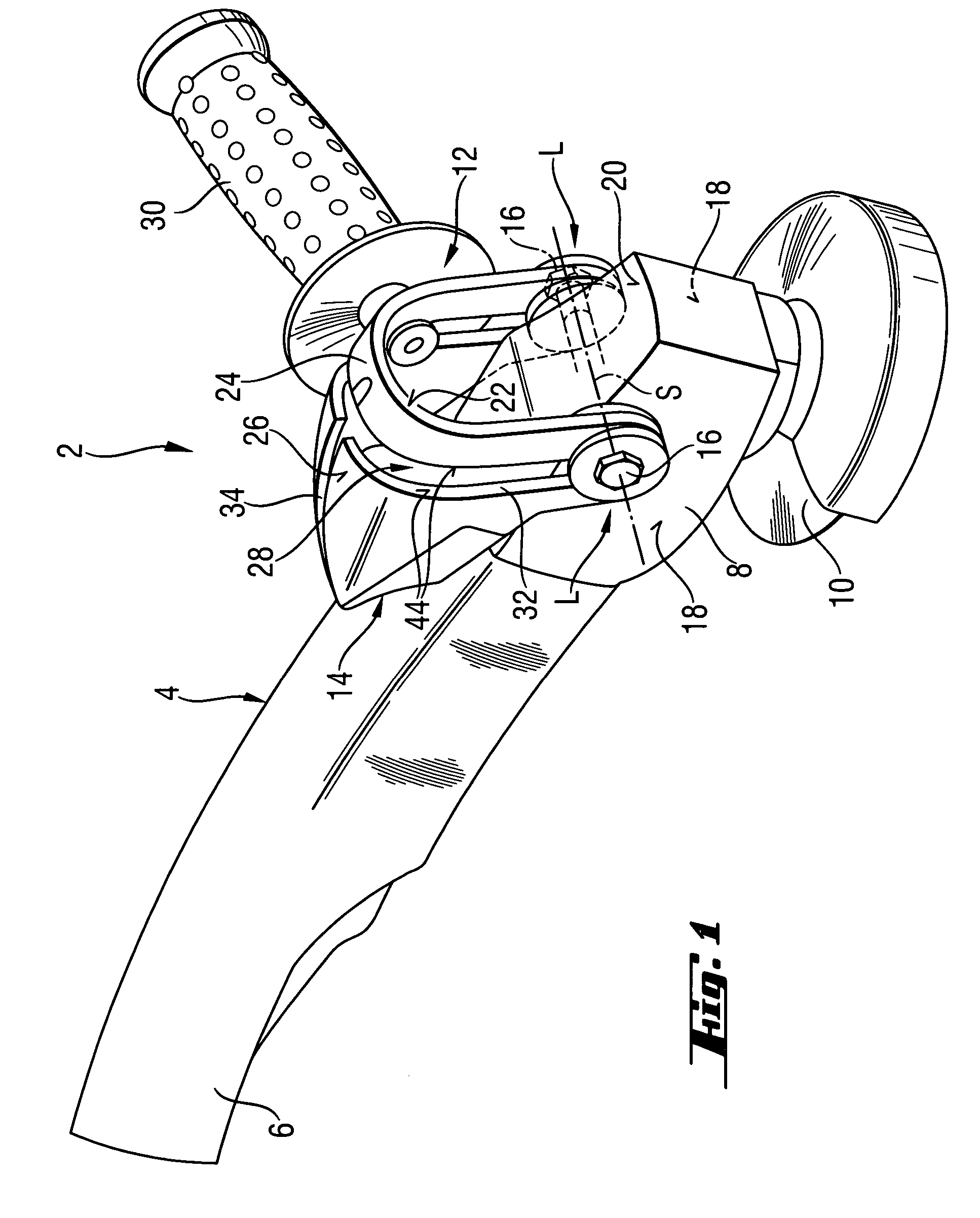
[0032]A power tool 2 according to the present invention, which is shown in FIG. 1, is formed as an angular grinder and includes a housing 4 forming a main handle 6. At its end remote from the handle 6, the housing 4 has a gear housing 8. In the gear housing 8, there is located a drive (not shown) for driving a tool disc 10 in form of a separating or grinding disc.

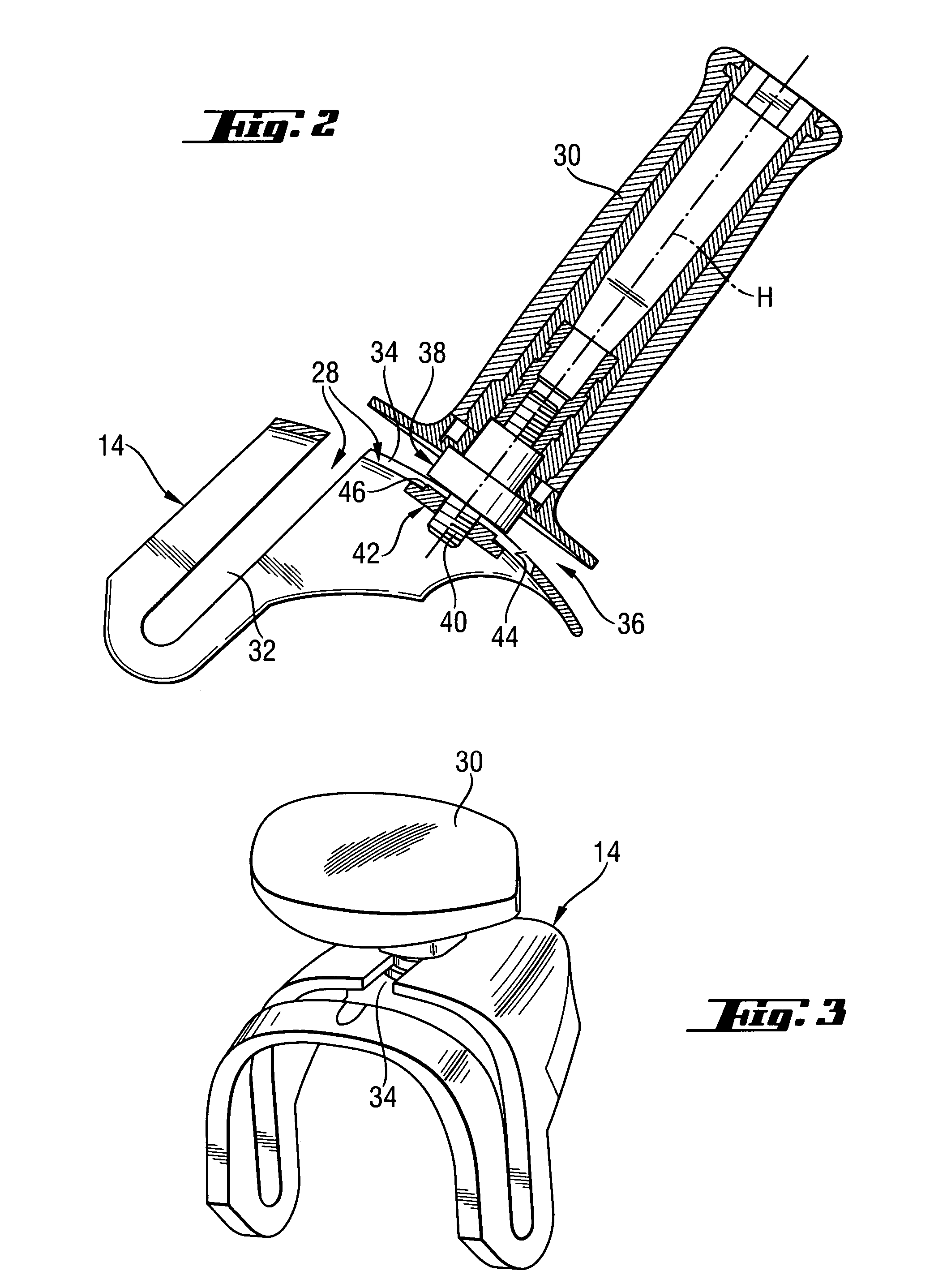
[0033]On the gear housing 8, an auxiliary handle 12 is arranged. The auxiliary handle 12 has a dome-shaped support member 14 rotatable about a pivot axis S. The pivot axis S is formed by two screws 16 screwed in at opposite side surfaces 18 of the gear housing 8 and holding the support member 14 on the housing 4. The support member 14 has a U-shaped profile surrounding the upper surface 20 of the gear housing 8. The support member 14 forms, at an end side 22 thereof, a stirrup handle 24 that can be used during operation for a stable holding of the power tool 2.

[0034]The dome-shaped profile of the support member 14 provides ...


PUM


Abstract

A hand-held power tool, such as an angular grinder, includes a housing having a main handle, and a support member for supporting a side handle in different positions relative thereto and pivotable relative to the housing about two support points, which may be on opposite side surfaces of the housing.

Description

BACKGROUND OF THE INVENTION[0001]1. Field of the Invention[0002]The present invention relates to a hand-held power tool and, in particular, an angular grinder including a housing having a main handle, a side handle, and a support member pivotable relative to the housing and supporting the side handle in different positions of the side handle relative to the support member.[0003]2. Description of the Prior Art[0004]In the power tools of the type described above, the position of the side handle relative to the main handle can be changed to adapt the arrangement of the handles to different applications and to provide for a good holding for each application. In addition, such hand-held power tools can be adapted without any problems to the use by both left-hander and right-hander.[0005]German Publication DE-197 45 306 discloses an angular grinder with a support provided on the grinder housing. The support has two receptacles for alternatively securing a side handle. Moreover, the suppor...

Claims


Application Information

Patent Timeline
Patent Type & Authority Patents(United States)
IPC IPC(8): B25G1/10B24B23/00A63B55/04B25C1/00B25F5/02
CPCB25F5/026Y10T16/4713Y10S16/90Y10T16/498Y10T16/50
Inventor KOSCHEL, CHRISTIANSPANGENBERG, ROLF
Owner HILTI AG
Why Eureka
Try Eureka