
Electric shaver floating head support structure

a technology of floating support structure and electric shaver, which is applied in the direction of metal working apparatus, etc., can solve the problems of limited head movement range, difficult size for comfortable hand fit, and limited head contours of head portion, so as to prevent the invasion of debris and water, and accurately follow the contours of skin.

Inactive Publication Date: 2005-05-17
MATSUSHITA ELECTRIC WORKS LTD
View PDF9 Cites 27 Cited by
  • Summary
  • Abstract
  • Description
  • Claims
  • Application Information

AI Technical Summary

Benefits of technology

[0010]The present invention, having taken the aforesaid shortcomings into consideration, offers an electric shaver floating head support structure through which the floating head is supported through a wide range of movement in order to accurately follow the contours of the skin, regardless of the attitude of the electric shaver, and which also prevents the invasion of debris and water into the electric shaver.
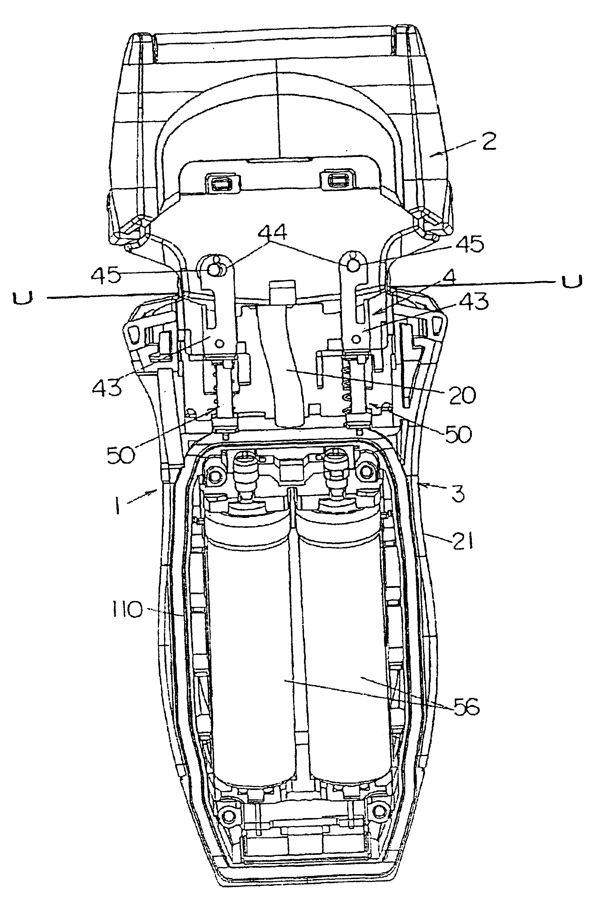
[0011]The present invention includes an electric shaver comprised of a head portion which incorporates a motor and shaving blades, and a grip portion that supports the free floating movement of the head portion. A box-like space (hereinafter referred to as a space) is formed within the grip portion beneath the lower surface of the head portion, and front and rear support walls extend upward beyond the space to sandwich the lower portion of the head portion at the forward and rearward facing sides. This structure firmly supports the head portion against pressure applied thereto in the fore-aft direction, thus allowing the user to hold the electric shaver by pressing against front and rear support walls with the thumb and fingers without the fingers entering the region in which head portion moves. This structure is able to provide a wide range of movement that allows the head portion to easily follow the contours of the skin being shaved, and thus improves the electric shaver's performance. The invasion of water and debris into the electric shaver is prevented through the head portion and the space of the grip being independently structured components.
[0012]It is preferable that spring articulation elements be installed between the head portion and the upper surface of the space in the grip. The spring articulation elements have no effect on the size of the grip, and thus allow the grip to be formed to a narrow contour that can be comfortably held in the hand. The spring articulation elements also provide for a more stable floating movement of the head.

Problems solved by technology

This structure poses a problem in that it largely restricts the lateral swinging movement of the head portion, and thus limits the ability of the head portion to follow the contours of the skin.
This structure allows the head to move only on the radial surface provided, thus limiting the range of movement of the head in relation to the grip, and thus preventing the head from moving in a way that could more accurately follow the contours of the skin being shaved.
Furthermore, the grip case must be made to a relatively large width, that is, a width greater than that of the head, to allow sufficient space for the movement of the motor which must laterally swing with the head, thus necessitating a grip that is difficult to size for a comfortable fit to the hand.
In this structure, the pivoting movement of the head results in the lower part of the head potentially swinging to a point that exceeds the boundary of the grip.
The head must thus be made to relatively small dimensions to prevent the lower part from coming into contact with the user's fingers holding the grip, thus necessitating that a correspondingly small motor be employed with the result that the electric shaver provides relatively weak shaving power.
A structure could be considered in which the location of the shaft on which the head rotates is lowered, but this could result, depending on the attitude of the shaver when held by the user, in the head freely rotating when separated from the skin, and thereby preventing the shaver from providing an adequate level of performance.

Method used


Image

  • Electric shaver floating head support structure
  • Electric shaver floating head support structure
  • Electric shaver floating head support structure

Examples


Embodiment Construction

[0040]The particulars shown herein are by way of example and for purposes of illustrative discussion of the embodiments of the present invention only and are presented in the cause of providing what is believed to be the most useful and readily understood description of the principles and conceptual aspects of the present invention. In this regard, no attempt is made to show structural details of the present invention in more detail than is necessary for the fundamental understanding of the present invention, the description is taken with the drawings making apparent to those skilled in the art how the forms of the present invention may be embodied in practice.

[0041]The following will describe an embodiment of the electric shaver head support structure of the present invention with reference to the attached drawings.

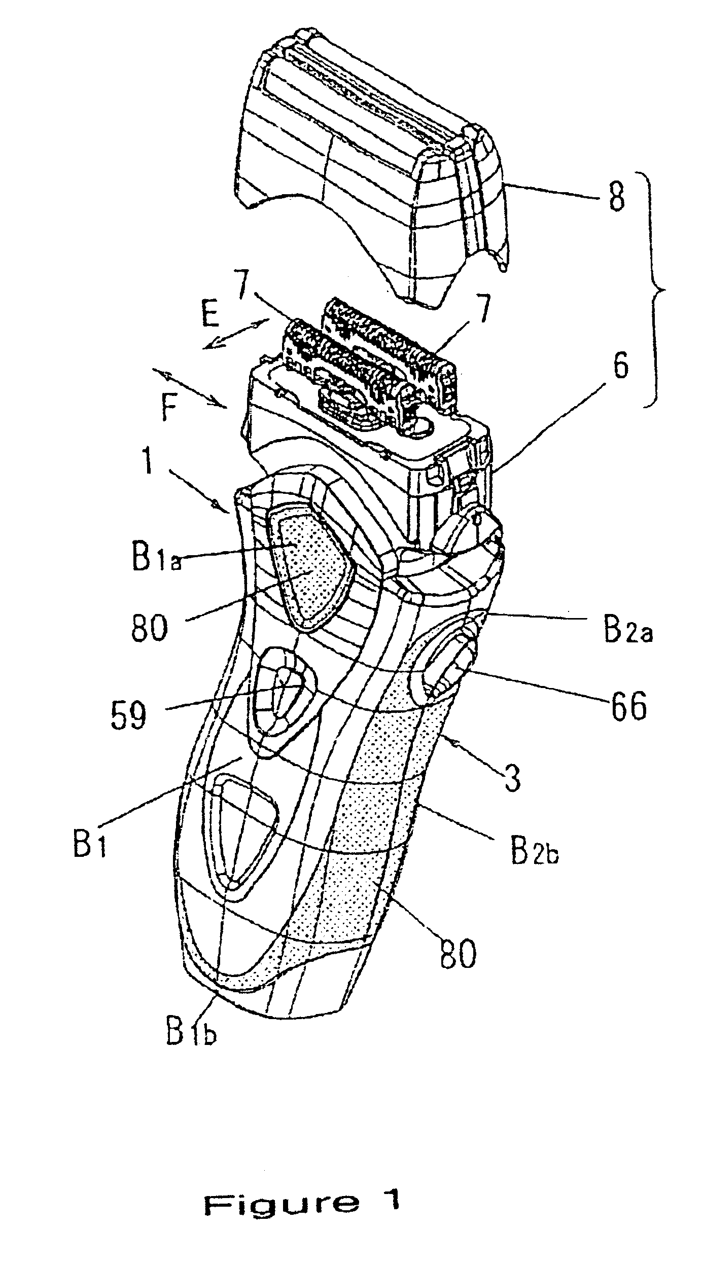
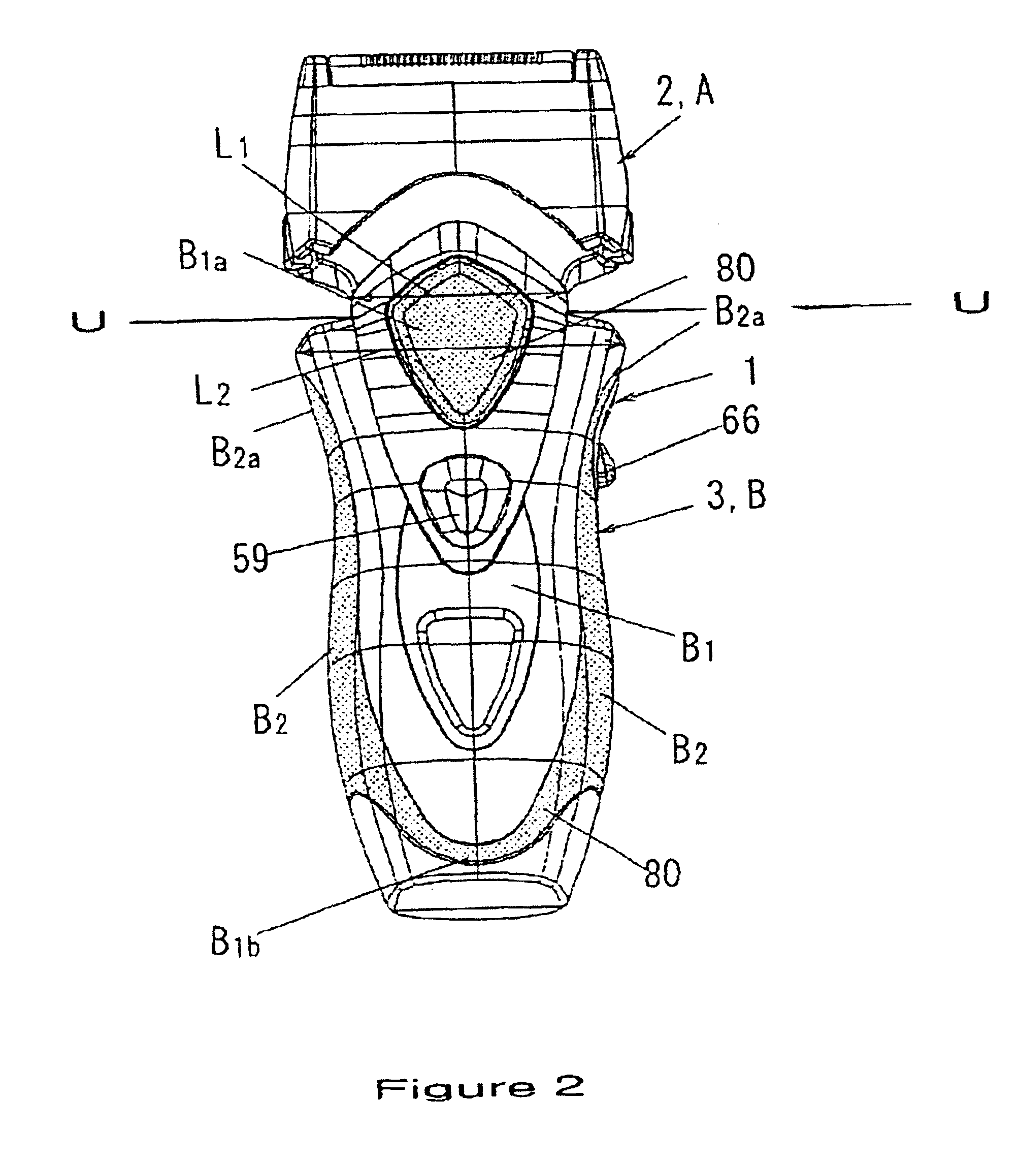
[0042]The electric shaver 1 of the present invention is illustrated in FIG. 1. The electric shaver 1 includes two separate components including a head body 2 and a grip ...


PUM


Abstract

A water and dust-proof electric shaver head support structure that provides a wide range of movement to the floating shaver head to closely follow the contours of the skin. The floating shaver head, which contains the motor and shaving blades, freely pivots in the lateral plane and telescopically floats in relation to the shaver grip. A box-like space is formed in the shaver grip below the lower surface of the shaver head, and front and rear support walls extend upward from the shaver grip to support the shaver head in the forward / rearward direction.

Description

BACKGROUND OF THE INVENTION[0001]1. Field of the Invention[0002]The present invention relates to a floating head support structure for an electric shaver in which the free articulated movement of the head portion in relation to the grip portion maintains improved contact between the shaving blades and the skin.[0003]2. Description of Related Art[0004]A conventional electric shaver of the type addressed by the invention incorporates a grip portion, a laterally pivotable head structured as a separate component from the grip portion, and a motor housed within the grip portion which is located beneath the head portion. This structure poses a problem in that it largely restricts the lateral swinging movement of the head portion, and thus limits the ability of the head portion to follow the contours of the skin.[0005]Various types of conventional electric shavers are structured to allow movement of the head in relation to the grip as a means of better maintaining the cutting blades in con...

Claims


Application Information

Patent Timeline
IPC IPC(8): B26B19/04B26B19/38B26B19/12B26B19/10
CPCB26B19/048B26B19/063B26B19/3866B26B19/38B26B19/3853B26B19/10B26B19/12
Inventor SHIBA, TAKESHITANIGUCHI, FUMIOYAMASAKI, MASANOBU
Owner MATSUSHITA ELECTRIC WORKS LTD
Learn More