Chair for a drum

a chair and drum technology, applied in the field of chairs for drums, can solve the problems of increasing fatigue, affecting the performance, and affecting the performance, so as to reduce fatigue or ache, and improve the cushioning

Inactive Publication Date: 2004-01-06
HOSHINO GAKKI COMPANY LIMITED
View PDF11 Cites 30 Cited by
  • Summary
  • Abstract
  • Description
  • Claims
  • Application Information

AI Technical Summary

Benefits of technology

The invention provides a chair structure with which the performer can perform pleasantly and in a stable posture, reducing fatigue or ache even during a long performance. The top side of the seat plate of the drum chair includes two concaves located below where the hip bones of the performer protrude down at both sides of the rear of the center of the seat plate, giving the seat plate an improved cushioning effect.
In another embodiment of a drum chair both the right and left sides of a bicycle seat shape seat plate are shaped as curved concaves capable of more comfortably holding the femoral regions of both legs of the performer. Alternatively, each curved concave region of the plate is a surface that becomes lower toward the edge.

Problems solved by technology

When a performance lasts a long time, e.g. an ordinary stage performance may last two to three hours and an ordinary recording session may take from seven to eight hours, the performer may become fatigued and may feel pain.
The performer may be operating the drum pedals with his heels raised from the floor, requiring that his weight be balanced by the seat surface alone and forcing him to adopt an unstable posture which would increase his fatigue.

Method used


Image

  • Chair for a drum
  • Chair for a drum
  • Chair for a drum

Examples


second embodiment

In FIG. 5, the concaves 12A and 13A for the hip bones in the chair 10A are oval in their peripheral shape, with their longer axis extending in the front and rear direction of the seat plate 11. The oval shape and orientation enable coping with variations in the posture of the performer, who might tend to sit more toward either the front or the rear than the chair designer might expect.

In the third embodiment 10B for the drum chair shown in FIG. 6, concaves 12B and 13B are also of an oval shape with the long axis forward and rearward. The concaves are provided in a seat plate 11B which is normally circular in shape as seen in the prior art.

The FIGS. 6 and 7 reference numbers corresponding to those in FIG. 1 are for the same structure.

fourth embodiment

In the chair 10C shown in FIG. 7, a single additional concave 16 for the region below the coccyx is placed below where the coccyx of the performer P (see coccyx 94 in FIG. 9) is situated, rearward of the concaves 12 and 13 toward the rear of the seat plate 11. A concave 16 below the coccyx enables mitigating fatigue and pain in the vicinity of the coccyx 94, helping the performer to maintain a satisfactory posture and concentrate on the performance.

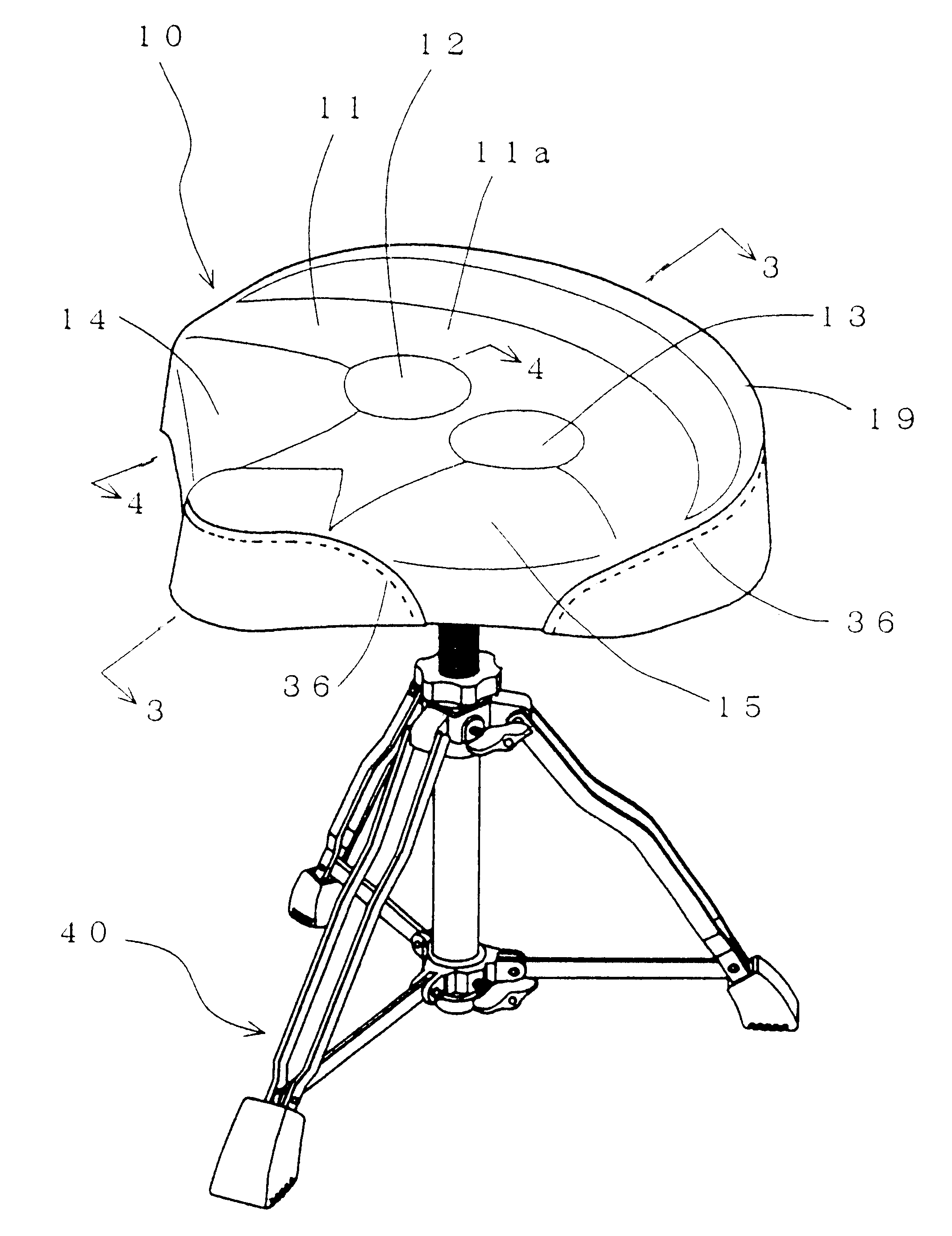
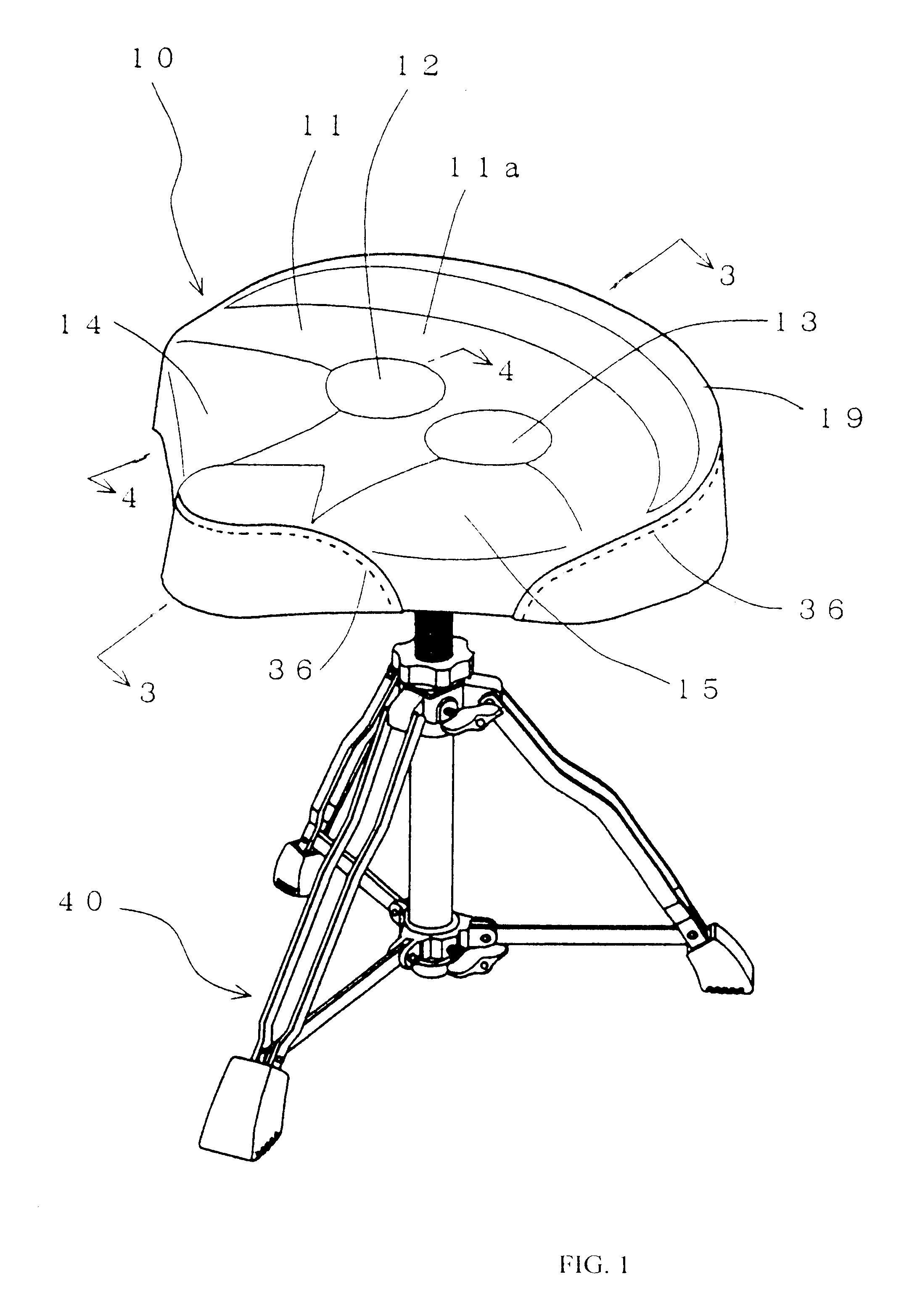
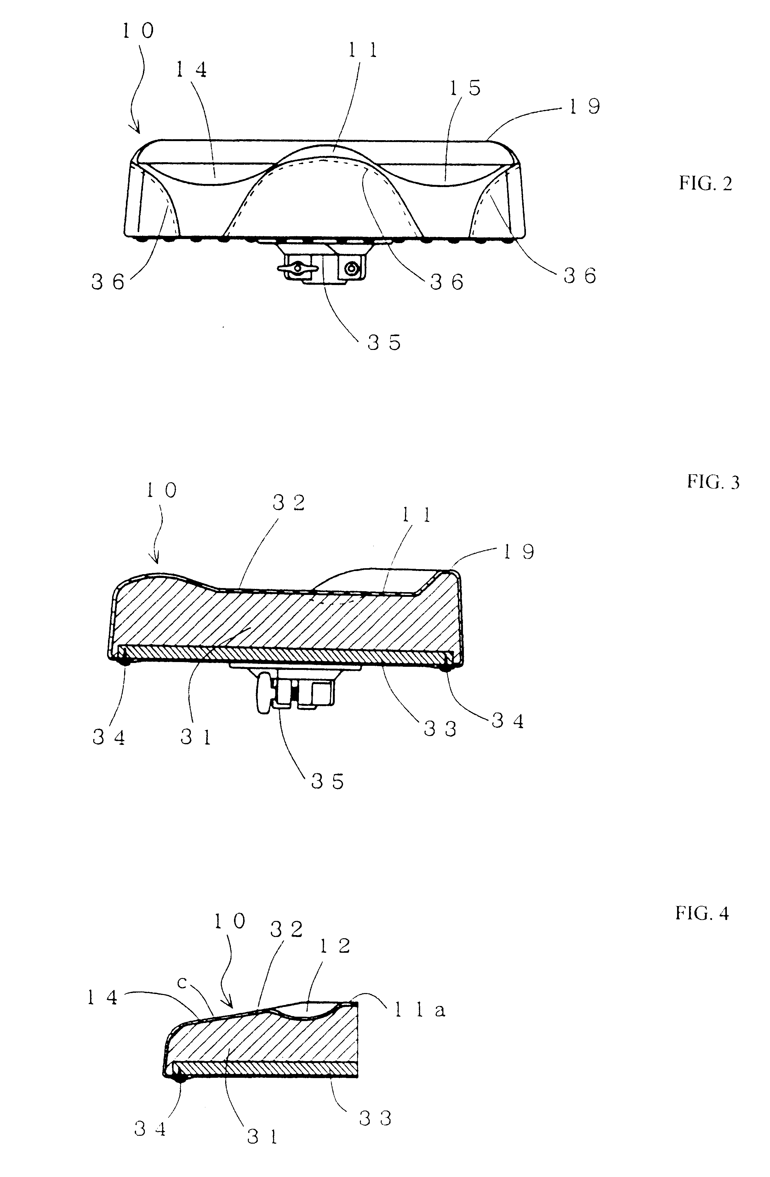
In the embodiments of the invention shown in FIGS. 1, 5 and 7, the right and left sides at the front of the seat plate 11 are each formed in the shape of curved concaves 14 and 15 which are capable of holding the femoral part 95 of both legs of the performer. It is preferable for each of the curved concaves 14 and 15 to be formed as a surface C which becomes gradually lower toward the edge of the seat plate, as in FIG. 4.

Stitching 36 is so placed along the edges of the seat plate 11 to avoid the stitching being felt around the femoral par...


PUM


Abstract

A chair having a seat plate supported by legs, the seat plate having a top side with two concaves therein below where a seated person's hip bones project and optionally an additional concave rearward of the two concaves and below where the seated person's coccyx projects. The positions of the concaves are selected to be where a performer on a drum is likely to be seated when playing a drum while seated. The two concaves may be circular or may be elongated in the forward-rearward direction. The seat plate may be circular or it may be a bicycle seat shaped with downward and outward sloping concaves for the femoral thigh regions at the sides and toward the front.

Description

The present invention relates to a drum chair used by a performer when playing a drum.A drum chair used when a drum is played ordinarily includes nothing similar to a back-rest, etc. that might obstruct a performer's movement since the performer usually moves rapidly or even violently while seated on the chair. Even when such a back-rest may be installed, it is positioned slightly toward the rear so as not to obstruct the movement of the performer. Its size is reduced to an extent such that it may not obstruct the performer's movement. As a result, the body weight of the performer is squarely placed on the drum chair.DESCRIPTION OF A PRIOR ART EMBODIMENTAn example of a prior art chair is shown in FIGS. 10 and 11. The most frequently used drum chair 50 shown in FIG. 10 has a round seat plate 51 which is almost flat on its top side and the seat plate is supported by legs 55. The drum chair embodiment 60 shown in FIG. 11 includes a seat plate 61 of a saddle type with a narrowed front t...

Claims


Application Information

Patent Timeline
Patent Type & Authority Patents(United States)
IPC IPC(8): A47C9/08A47C9/00A47C7/02G10G7/00G10D13/00
CPCA47C9/08A47C7/029
Inventor HOSHINO, YOSHIHIRO
Owner HOSHINO GAKKI COMPANY LIMITED
Why Eureka
Try Eureka