Fluidtight slide fastener

a slide fastener and fluid-tight technology, which is applied in the field of fluid-tight slide fasteners, can solve the problems of loss of the required fluid-tight features of the slide fastener, complicated process for manufacturing the slide fastener, and difficulty in reliably joining the tapes to the material of the suit/garment where the slide fastener is manufactured, so as to achieve good fluid-tight requirements, reduce costs, and easy to carry ou

Inactive Publication Date: 2008-07-01
RIRI GROUP
View PDF15 Cites 9 Cited by
  • Summary
  • Abstract
  • Description
  • Claims
  • Application Information

AI Technical Summary

Benefits of technology

[0018]It has been surprisingly found that a slide fastener as above shows good fluidtight requirements in the long run while at the same time it can be obtained in a simple manner and at reduced costs as the welding or sealing step can be easily carried out and integrated in conventional manufacturing processes of fluidtight slide fasteners. In particular, as it will be clearly explained later on, the sealing or welding step can be implemented together with the cutting step of strips coated with a fluid-barrier material from which the tapes are obtained. According to another embodiment of the present invention, said coating is at least a cap applied on each tape at said at least one of said uncoated short edges for covering the textile material strip in a fluidtight way at said at least one of said uncoated short edges.
[0019]In this way, it is achieved the additional advantage of strengthening the slide fastener at its short edge(s) to which the cap is applied so rendering the slide fastener in particular more resistant to wear.

Problems solved by technology

However, due to the cutting step, the textile material of each tape remains uncoated at least one of the short edges thereof.
As a result, the fluids, in particular water, may seep in the textile material strip of the tapes, causing in a long run an undesired swelling of the tape itself or even separation (delamination) of the coating of the fluid-barrier material from the textile material strip, which finally leads to the loss of the required fluidtight features of the slide fastener.
This problem may result as a consequence of subjecting the slide fastener to fluids (for example water) both during the normal use of the garment incorporating it and during (intensive) washing cycles of said garment.
Although advantageous from various points of view, a fluidtight slide fastener of the type schematically described above has recognized drawbacks, the first of which is linked to the fact that the process for manufacturing the slide fastener is complicated due to the provision of such folding and welding steps of the tape ends.
Another drawback of the fluidtight slide fastener structured in the way schematically described above, is that the folded portions thicken the tapes at the folded short edges, so that it is difficult to reliably join the tapes to the material of the suit / garment where the slide fastener has to be applied.
Moreover, in some appliances, such as diving suit for deep sea use, the above process cannot be applied since the tape are obtained in a so thick and rigid structure that they cannot be suitably folded.

Method used


Image

  • Fluidtight slide fastener
  • Fluidtight slide fastener
  • Fluidtight slide fastener

Examples


second embodiment

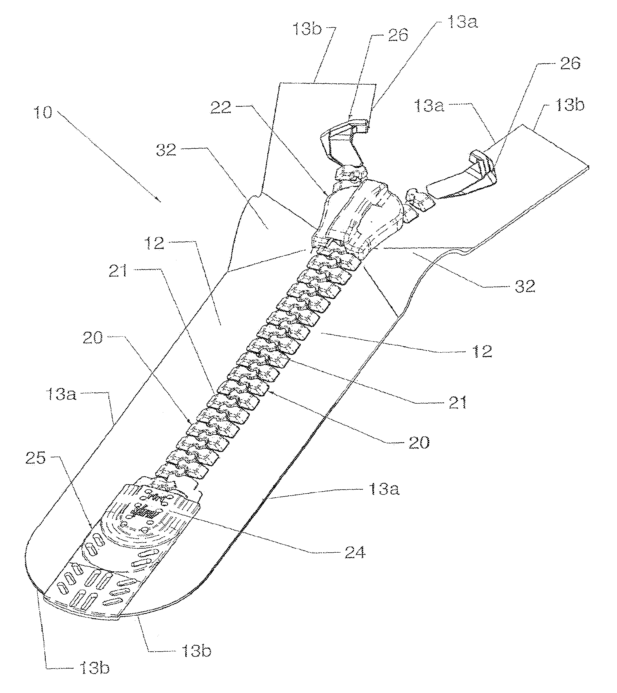
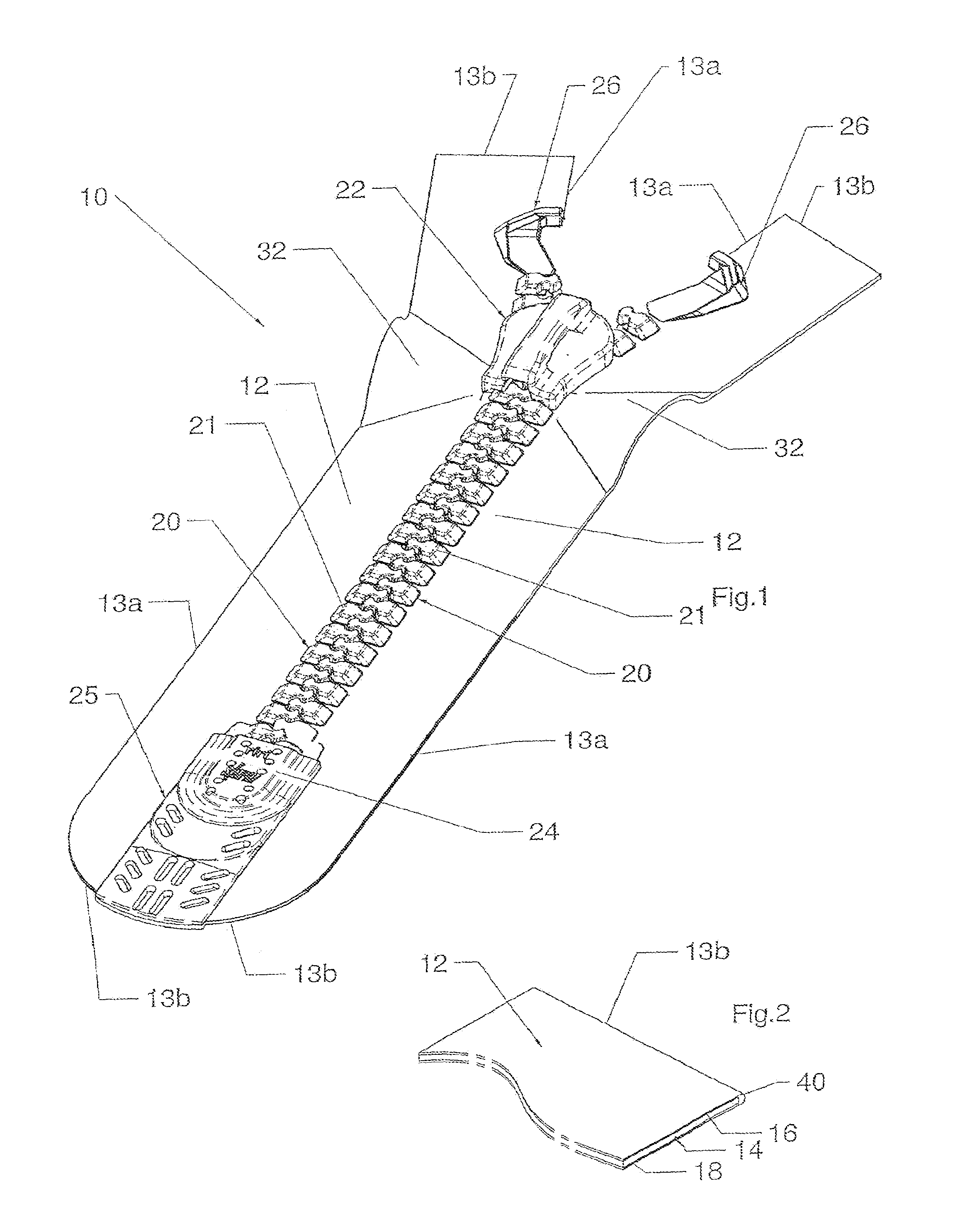
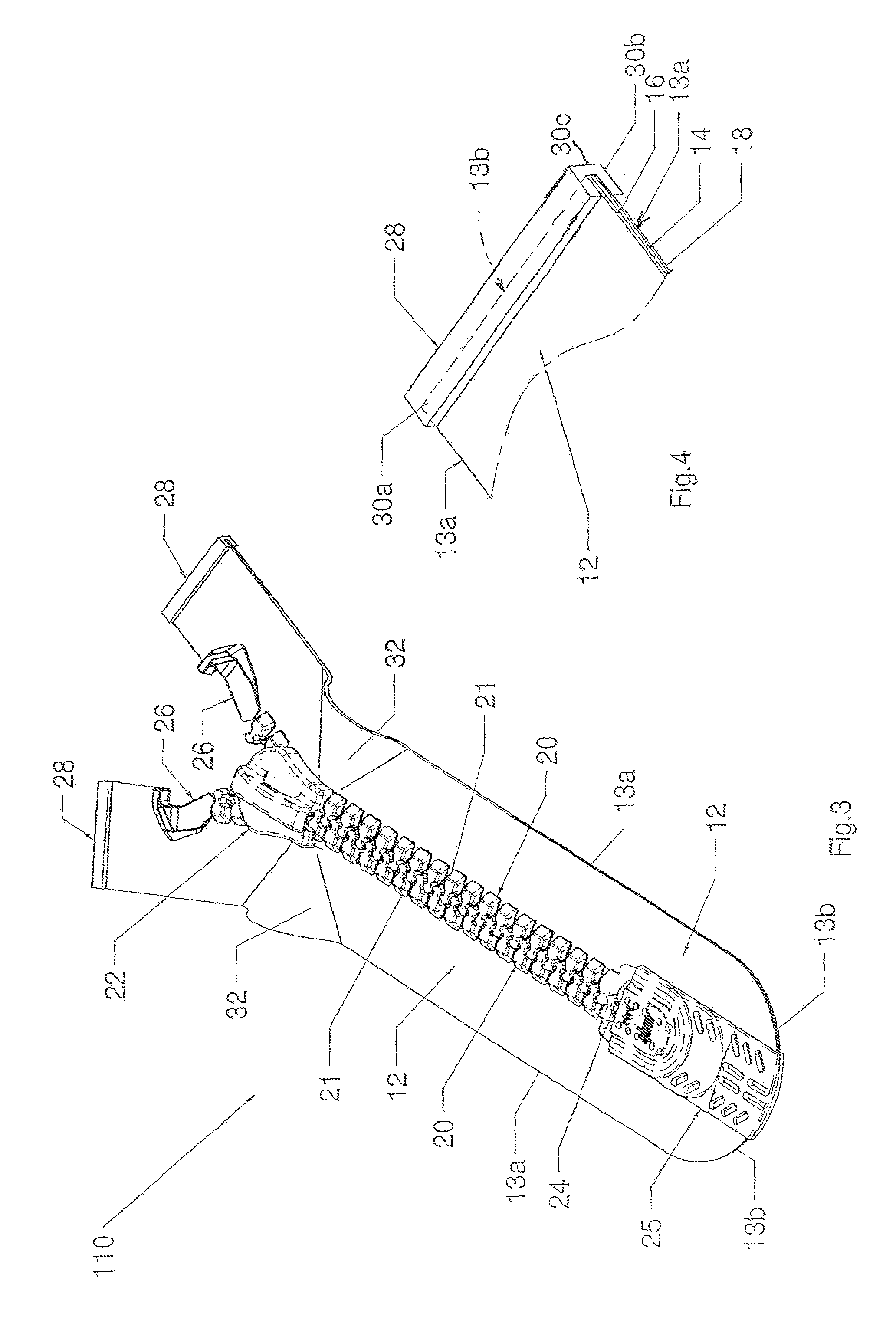
[0059]With reference now to FIGS. 3-8, a fluidtight slide fastener according to the present invention, globally indicated with 110, is now described.

[0060]In the slide fastener 110, elements structurally and / or functionally equivalent to those of the slide fastener 10 are indicated with the same reference numerals, and the description thereof is not repeated.

[0061]The slide fastener 110 substantially differs from the slide fastener 10 described above in that each tape 12 is obtained from an original strip forming said tapes 12 with upper short edges 13b being uncoated with fluid-barrier material of fluid-barrier layers 16 and 18 and that two caps 28, structurally and functionally identical, are applied in a fluidtight way to a respective tape 12 at the upper short edge 13b thereof, i.e. the short edge 13b proximate to the relative closing stop 26, to fully cover the textile material strip 14 in correspondence with the upper short edges 13b of the tapes 14.

[0062]In more detail, the c...

third embodiment

[0067]With reference now to FIGS. 9 and 10 a fluidtight slide fastener according to the present invention, globally indicated with 210, is now described. In the slide fastener 210, elements structurally and / or functionally equivalent to those of both the slide fastener 10 and the slide fastener 110 are indicated with the same reference numerals, and the description thereof is not repeated.

[0068]As in the slide fastener 110 described above, the slide fastener 210 has two tapes 12 formed with upper short edges 13b being uncoated with fluid-barrier material of fluid-barrier layers 16 and 18.

[0069]In addition, the slide fastener 210 has two caps 128, structurally and functionally identical, which are applied in a fluidtight way to a respective tape 12 at the upper short edge 13b thereof, i.e. the short edge 13b proximate to the relative closing stop 26, to fully cover the textile material strip 14 in correspondence with the upper short edges 13b of the tapes 14.

[0070]In particular, in t...


PUM


Abstract

A fluidtight slide fastener comprising a pair of tapes comprising a textile material strip coated with a fluid barrier material layer and equipped with a set of aligned teeth, an opening stop and an opposite closing stop, a slider for engaging in a fluidtight way or disengaging said teeth respectively, wherein the fastener comprises a further fluid-tight coating formed on at least one short edge of the tapes.

Description

FIELD OF APPLICATION[0001]The present invention, in its most general aspect, refers to a slide fastener.[0002]In particular, the invention refers to a fluidtight slide fastener, i.e. a slide fastener that is impermeable to fluids.[0003]In the following description, the term “fluidtight” means a sealing that prevents the passage of liquids, in particular water, and / or gases, for example air, even if put under pressure within predetermined high limits, for example till about 2 bar of pressure difference between the interior and exterior sides of the slide fastener.[0004]More in particular, the present invention refers to fluidtight slide fastener of the type comprising a pair of tapes both delimited by two opposite long edges and by two opposite short edges, each tape comprising a textile material strip coated with a fluid barrier material at least in correspondence with the opposite faces thereof, each tape being equipped with a set of aligned teeth on at least a portion of one of sa...

Claims


Application Information

Patent Timeline
Patent Type & Authority Patents(United States)
IPC IPC(8): A44B19/32
CPCA44B19/32Y10T29/49888Y10T24/2514Y10T29/49782Y10T29/49785Y10T24/2593Y10T29/49885Y10T29/53291
Inventor COSSUTTI, LIVIO
Owner RIRI GROUP
Why Eureka
Try Eureka