

Padded shoe
- Summary
- Abstract
- Description
- Claims
- Application Information
AI Technical Summary
Benefits of technology
Problems solved by technology
Method used
Image

Examples
Embodiment Construction
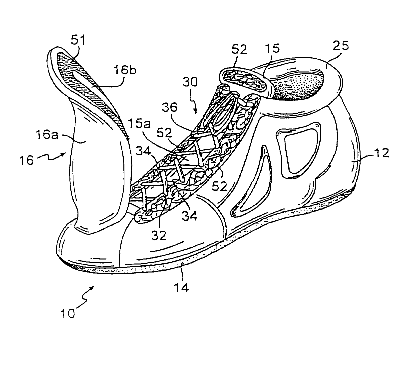
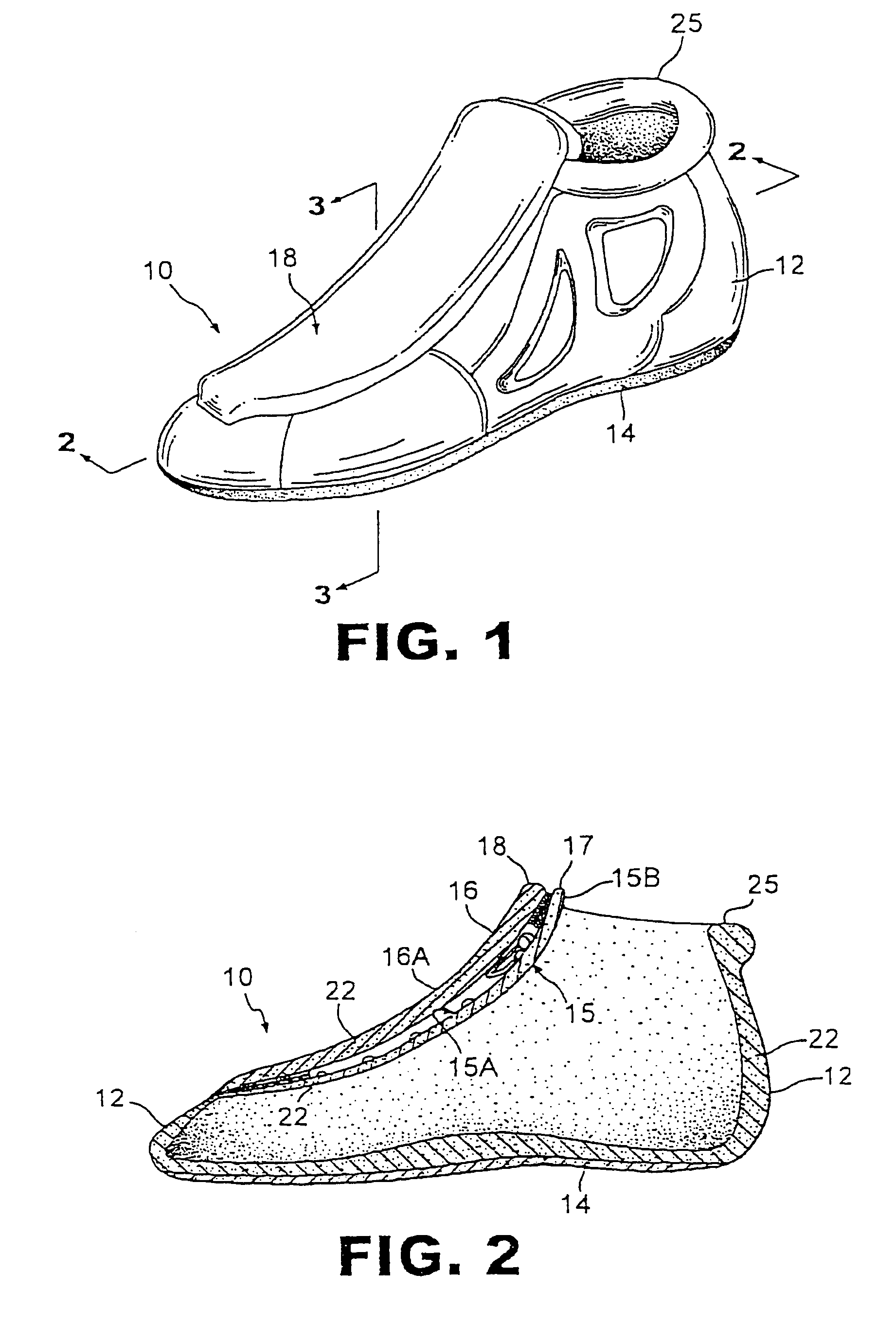
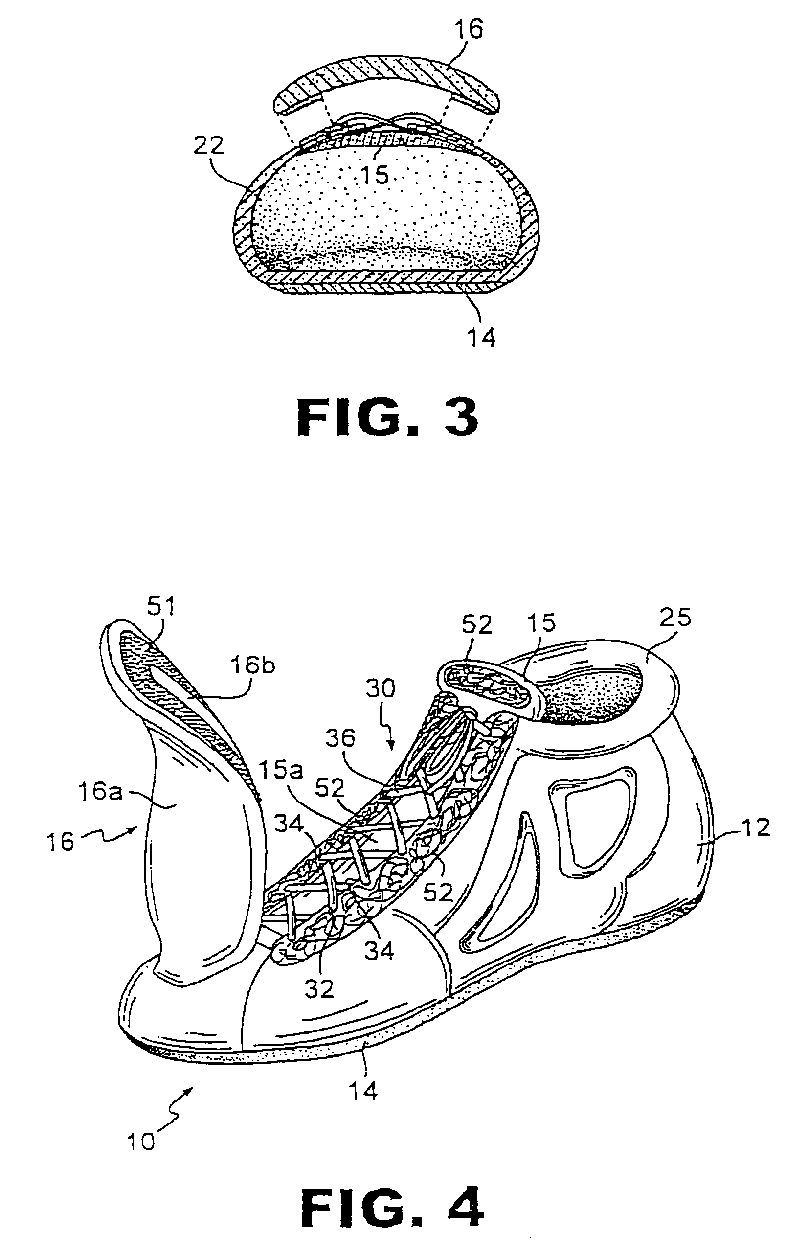
[0035]A shoe 10 according to a one embodiment of the invention is illustrated in FIG. 1. The shoe 10 is preferably formed of materials which are light in weight yet still strong and durable. The shoe 10 includes a shoe upper 12 adjoined to a sole 14. The shoe upper 12 can be manufactured from any conventional material such as leather, synthetic leather, or canvas. The shoe upper 12 preferably extends at least to the ankle of the wearer, however, the invention is not limited in that regard. For example, the shoe upper 12 can extend significantly beyond the ankle of the wearer to cover all or a portion of the shin, or not extend to the ankle of the wearer. The upper edge 25 of the shoe upper 12 preferably forms a collar into which a foot can be inserted.
[0036]A portion of the edge of sole 14 can be chamfered to provide a continuous arcuate edge at the point where the sole 14 is joined to the shoe upper 12. It is particularly preferable to have chamfered edges at the front toe and rear...
PUM
 Abstract
Description
Claims
Application Information