Rail guide for a suspended and guided sliding component

a technology of sliding component and rail guide, which is applied in the direction of rope railways, curtain suspension devices, railways, etc., can solve the problems of not being able to branch into a stacking position, not being realized, and only being able to reach the stacking position

Active Publication Date: 2008-07-01
DORMAKABA DEUT GMBH
View PDF9 Cites 22 Cited by
  • Summary
  • Abstract
  • Description
  • Claims
  • Application Information

AI Technical Summary

Benefits of technology

[0009]It is an object of the invention to provide a rail guide in which the rail itself is improved, particularly in relation to the manufacturing process, wherein the rail profile and the corresponding embodiment of the carriage in a branching region of a stacking area, allows for abandoning a turnout without modifying the profile. Furthermore, substantially over the displacement path of the sliding component, that is to say over the so-called main track, the complete profile of the rail guide should possibly be used by the carriage. Finally, a particular embodiment of the guiding rails should guarantee a smooth transition from one rail section to an adjoining rail section.
[0010]According to the invention, two profiles of a guiding rail are used, which are inexpensive in manufacturing and shaping, and can be joined to form a smooth rail guide, whereby the assignment and embodiment of the carriages allows for the support of the carriages at the entire rail guide over the main track and the branching can be realized without needing a turnout.
[0012]In order to guarantee the above described guiding function, it has proven to be advantageous that a flange, oriented against the carriage, is positioned at the free end of the upper horizontal leg of the guiding rail. The flange practically guarantees the positive guidance on both sides of the higher formed guiding roller.

Problems solved by technology

In the aforementioned known device, a branching into a stacking position is only possible by utilizing an additional expensive turnout.
The known device is particularly disadvantageous in that each carriage, in the region of the main track, is only supported either in the left region or in the right region of the guiding rail, that is to say, only half of the provided profile is used by the respective carriage.
A branching is obviously not intended, and likewise could not be realized because of the trunnion that is common to the guiding rails.
Moreover, the known structure requires an extraordinary construction width and increased technical expense.

Method used


Image

  • Rail guide for a suspended and guided sliding component
  • Rail guide for a suspended and guided sliding component
  • Rail guide for a suspended and guided sliding component

Examples


Embodiment Construction

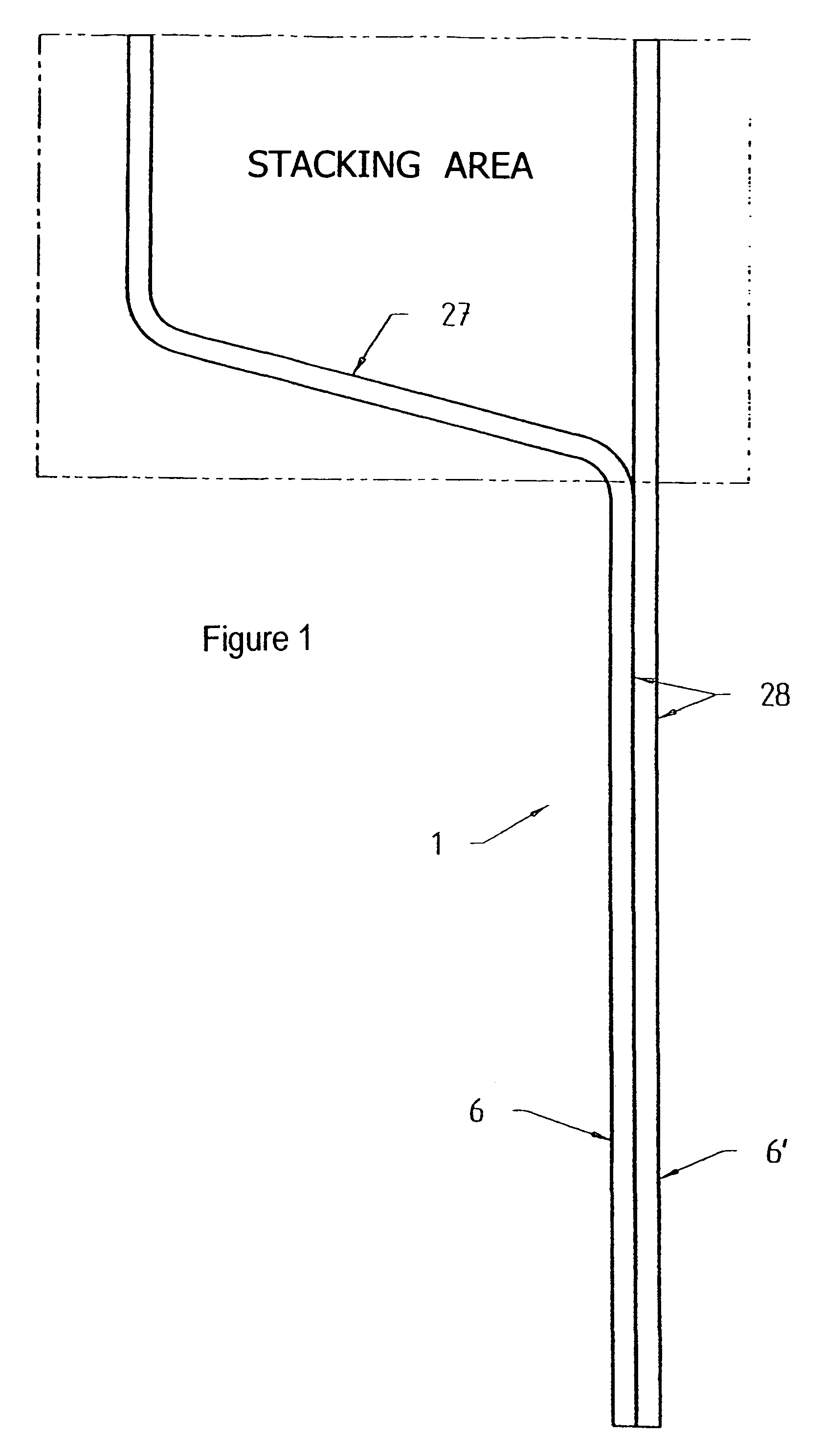
[0019]FIG. 1 shows a rail guide 1 which, in the region of a main track, consists of guiding rails 6 and 6′ joined to form a line of rails 28. In this case the guiding rail 6 is formed with a branch 27 leading into a stacking area.

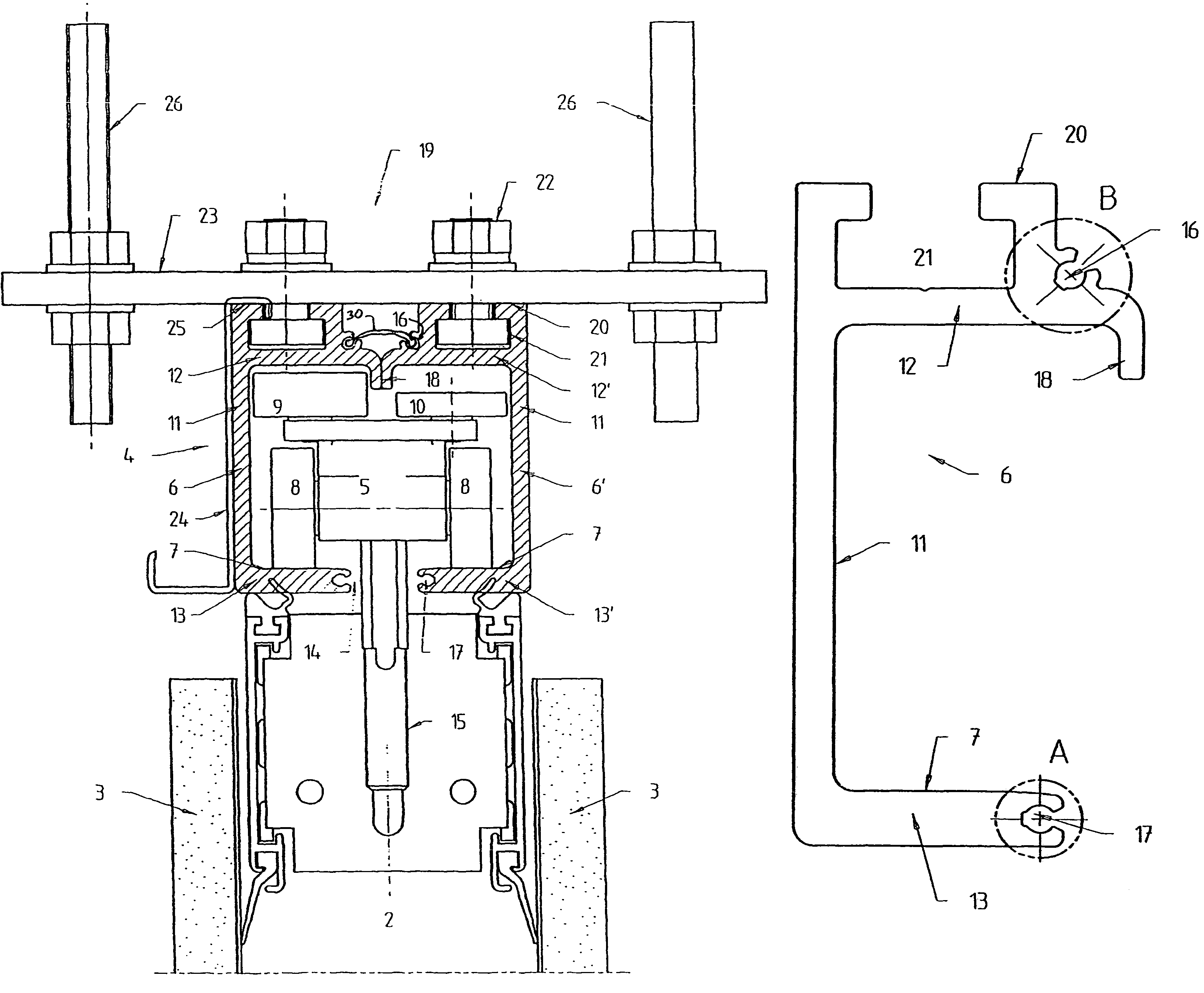
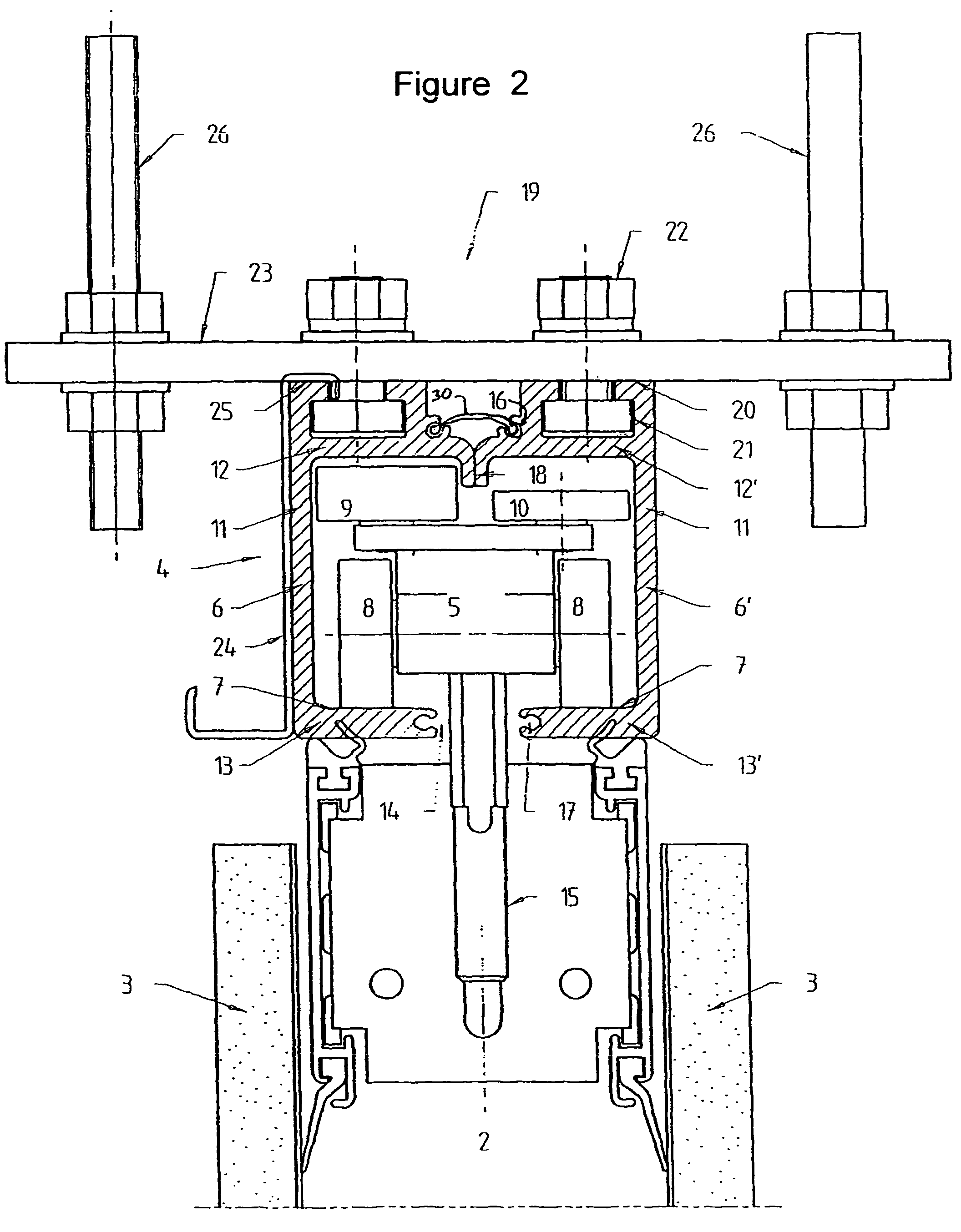
[0020]According to the cross sectional illustration of FIG. 2, a sliding component 2, presenting two panels 3 in this embodiment example, is suspended from a carriage 5 via a suspension bolt 15. The separate guiding rails 6 and 6′, which have identical profiles and are disposed mirror-inverted with regard to one another, each includes a vertically extending strut 11, upper legs 12 and 12′ disposed facing each another, as well as lower legs 13 and 13′ disposed facing each another, between which a longitudinal slot 14 is left for the passage of the suspension bolt 15. A running mechanism 4, including support rollers 8 rolling on running paths 7 of the lower horizontal legs 13 and 13′ as well as guiding rollers 9 and 10, is assigned to the carriage 5. In relat...


PUM


Abstract

A rail guide having first and second guiding rails disposed in a mirror-inverted relationship with regard to one another. At least one pair of spaced leading and following carriages are displaceably mounted to the guiding rails so as to engage and transport a sliding component along a transport path towards a stacking area. While the leading and following carriages are slidably supported by both guiding rails along the main track of the transport path, the leading carnage slides along the first rail, and the trailing carriage slides along the second rail along the transport path downstream from the main track in the stacking area.

Description

PRIORITY CLAIM[0001]This is a U.S. national stage of application No. PCT / EP2004 / 005311, filed on 18 May 2004. Priority under 35 U.S.C. §119(a) and 35 U.S.C. §365(b) is claimed from German Application No. 103 23 274.5, filed 21 May 2003.BACKGROUND OF THE INVENTION[0002]1. Field of the Invention[0003]The invention relates to a rail guide for a suspended and guided sliding component.[0004]2. Description of the Related Art[0005]The sliding components guided in the aforementioned rail guide may be executed differently, for example as wood panels or glass panels, in simple or double disposition. In the extended disposition, the sliding components form a closed wail and they can be displaced by guiding them in the rail guide into a stacking area, normally in a side-by-side disposition. Generally, two carriages are assigned to each sliding component. Provided that the spaced apart carriages supporting a sliding component are guided at a single guiding rail only, one turnout is required for ...

Claims


Application Information

Patent Timeline
Patent Type & Authority Patents(United States)
IPC IPC(8): E05D15/00E05D15/06
CPCE05D15/0608Y10T16/376E05Y2900/142
Inventor KSYK, ANDREAS
Owner DORMAKABA DEUT GMBH
Why Eureka
Try Eureka