Supercharge Your Innovation With Domain-Expert AI Agents!

Chuck in a processing machine

a processing machine and chuck technology, applied in the field of chucks, can solve the problems of poor processing work, uneven processing procedure, and poor processing procedure precision

Inactive Publication Date: 2008-07-01
CHEN CHIN CHIU
View PDF13 Cites 3 Cited by
  • Summary
  • Abstract
  • Description
  • Claims
  • Application Information

AI Technical Summary

Benefits of technology

"The present invention is a chuck that includes a conical connecting portion, a head, and a flange portion sandwiched between the connecting portion and the head. The flange portion has a larger dimension than the bottom most face of the connecting portion and a shoulder on its top face. An annular pad is provided on the shoulder of the flange portion to compensate for the gap between the chuck and the processing machine and secure engagement between the chuck and the processing machine, thereby reducing vibration and friction. The technical effect of the invention is to improve the stability and reliability of the chuck during processing."

Problems solved by technology

That is, during the process, if the chuck for holding the processing blade is not firmly secured to the processing machine, vibration between the chuck and the processing machine causes bad processing work.
Also, the processing procedure is not smooth.
Due to the existence of the gap (A), vibration of different levels often cause bad precision in the processing procedure.
Furthermore, friction between the outer periphery of the connection portion (51) and an inner periphery of the conical indentation (61) causes wear to the chuck (50), which deteriorates the connection between the chuck (50) and the processing machine (60).

Method used


Image

  • Chuck in a processing machine
  • Chuck in a processing machine
  • Chuck in a processing machine

Examples


Embodiment Construction

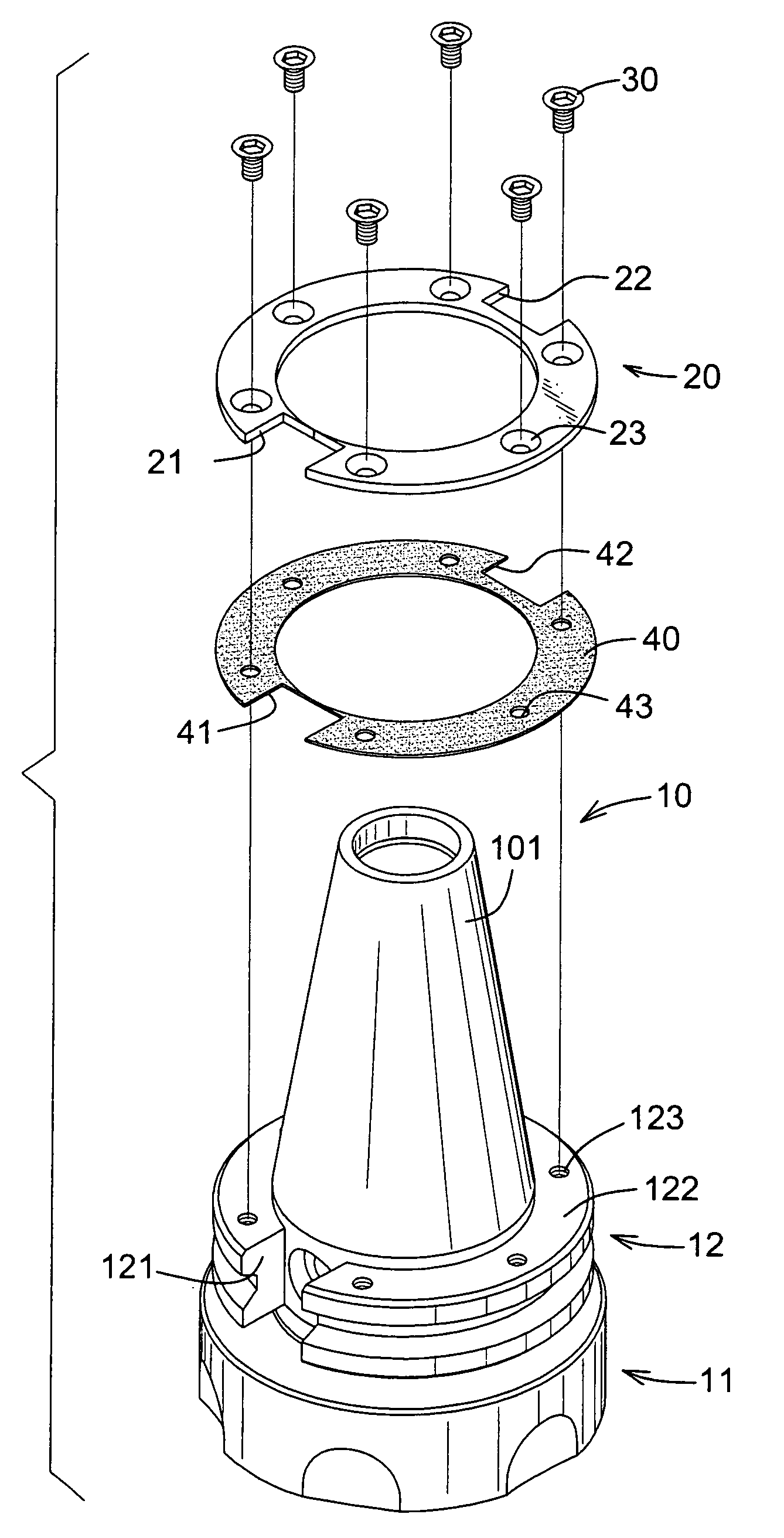
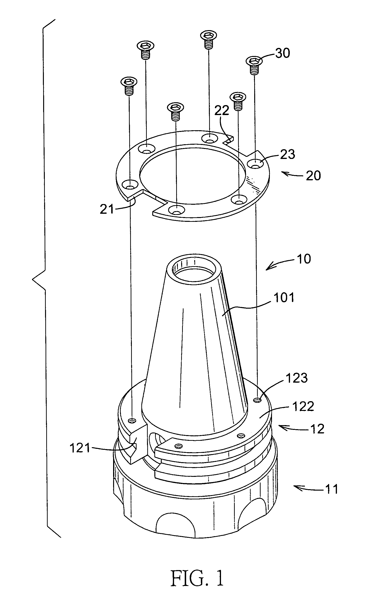
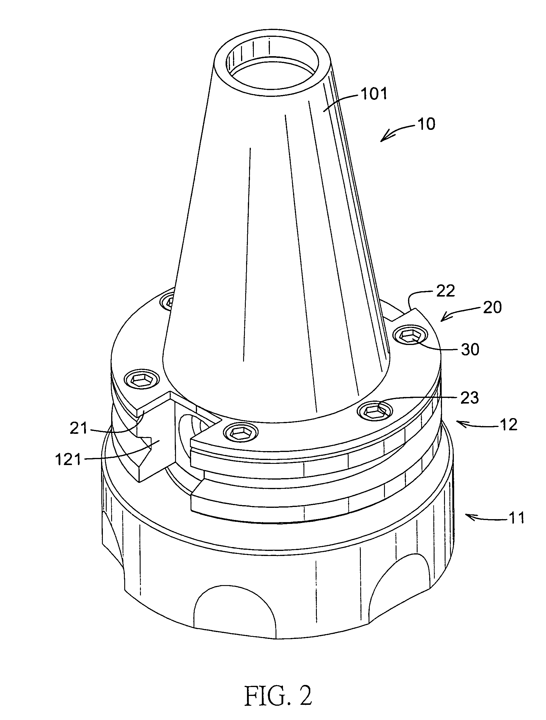
[0021]With reference to FIG. 1, it is noted that the chuck (10) in accordance with the present invention includes a conical connecting portion (101), a head (11), and a flange portion (12) sandwiched between the head (11) and the conical connecting portion (10). The head (11) is configured to hold a blade (not shown) and the flange portion (12) is provided with a cutout (121) defined in a side face thereof. A shoulder (122) is formed on a top face of the flange portion (12) and multiple threaded holes (123) (six are shown) are defined in a face of the shoulder (122). An annular pad (20) is mounted around the connecting portion (101) and provided with a first cutout (21) corresponding to the cutout (121) of the flange portion (12), a second cutout (22) opposite to the first cutout (21) and multiple countersunk holes (23) defined through the annular pad (20) and having a quantity substantially the same as that of the threaded holes (123) of the flange portion (12). Multiple threaded b...


PUM

PropertyMeasurementUnit
friction wearaaaaaaaaaa
dimensionaaaaaaaaaa
frictionaaaaaaaaaa

Abstract

In a chuck adapted for connection to a processing machine and composed of a connecting portion adapted to extend into the processing machine so as to securely engage the processing machine, a head adapted for holding a blade, and a flange sandwiched between the head and the connecting portion thereby / defining a gap between the flange and a bottom face of the processing machine, the improvement including: a shoulder formed on a top face of the flange portion; an annular pad supported on the shoulder of the flange portion and adapted to be mounted around the connecting portion; and a secondary annular pad mounted on and supported by the shoulder of the flange portion, and sandwiched between the shoulder and the annular pad, whereby the gap between the flange portion and a bottom face of the processing machine is compensated for by existence of the annular pad.

Description

BACKGROUND OF THE INVENTION[0001]1. Field of the Invention[0002]The present invention relates to a chuck, and more particularly to a chuck in a processing machine capable of securing the blade during the processing procedure without the worry of vibration and friction wear to the parts of the chuck.[0003]2. Description of the Related Art[0004]A processing machine or a lathe is used to work on an object to produce a requited item. During the processing procedure, normally a processing blade is the key to the work. Despite the sharpness issue of the blade, there is something that deserves attention. That is, during the process, if the chuck for holding the processing blade is not firmly secured to the processing machine, vibration between the chuck and the processing machine causes bad processing work. Also, the processing procedure is not smooth.[0005]In order to have a better understanding of the conventional problem, reference is made to FIG. 10, in which, a conventional chuck (50)...

Claims


Application Information

Patent Timeline
Patent Type & Authority Patents(United States)
IPC IPC(8): B23Q3/12
CPCB23B31/006B23B2231/0292B23B2250/16Y10T409/30952Y10T409/309408Y10T279/34B23B2260/114
Inventor CHEN, CHIN-CHIU
Owner CHEN CHIN CHIU
Features
  • R&D
  • Intellectual Property
  • Life Sciences
  • Materials
  • Tech Scout
  • Unparalleled Data Quality
  • Higher Quality Content
  • 60% Fewer Hallucinations
Learn More